September 23, 2024
A variation to a common American Flyer crane by Ben Swope

Being an avid collector of American Flyer items, other Gilbert products seem to find their way home too, including several Erector sets. Sometimes, a project merges these Gilbert products to create a new variation.
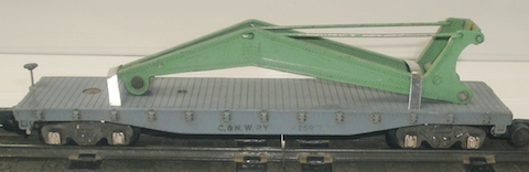
As I was digging through a box of stored “basket case” condition American Flyer rolling stock, when I ran across what was once a #606 crane someone customized for their own S-gauge pike. The previous owner discarded the railcar underframe, replacing it with a shorter solid wood frame, assumingly to make it look more like a lighter capacity wrecking crane.
With the short frame, it also resembled a locomotive crane, being a common crane used in scrap yards, steel mills or lighter lifting needs by many railroads. To further the conversion to a locomotive crane, all it needed was to replace the original curved wrecking crane boom for a straight lattice-type boom. Attempting to reason what the design engineers of Gilbert would have done for such a conversion, I turned to my collection of Erector sets.
By using two Erector 10-inch lattice girder sections to replace the original boom, I thought the conversion could be pulled off, so I raided the Erector boxes for more parts. The project has the look of yet another variation to this common American Flyer crane body using mostly Gilbert items.
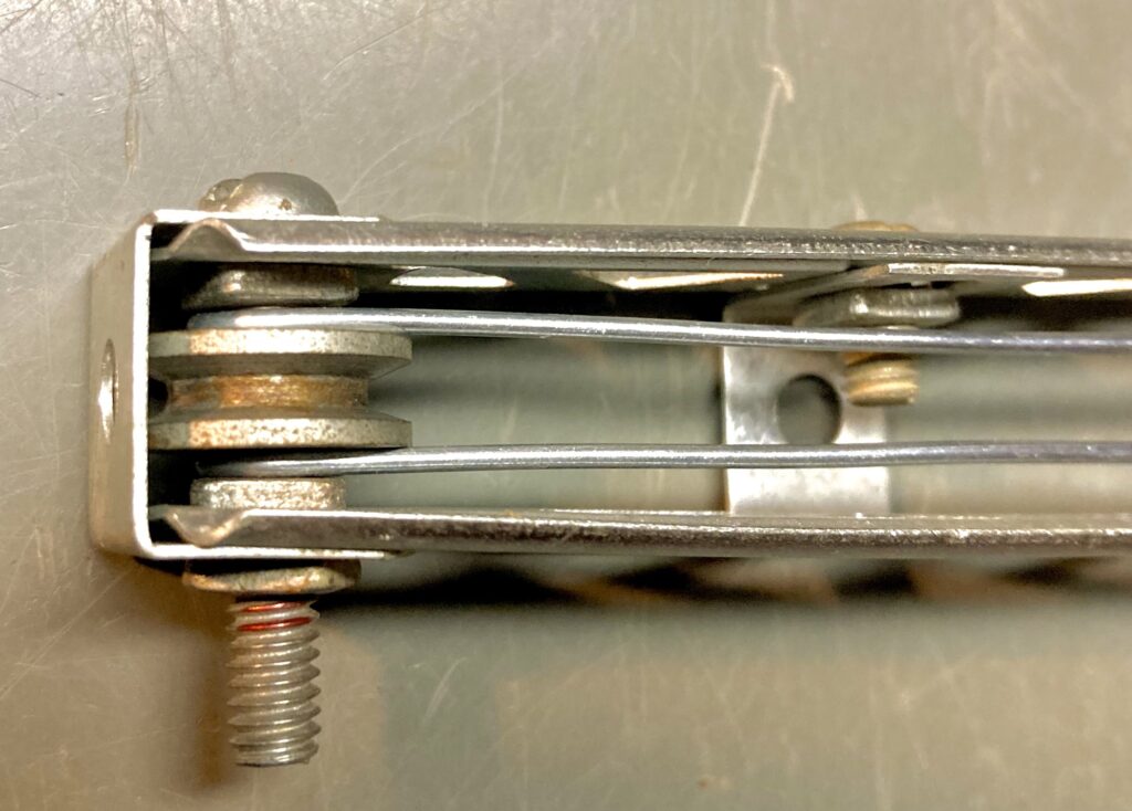
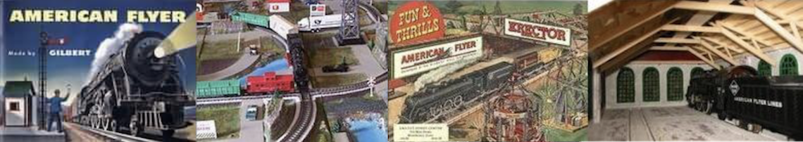
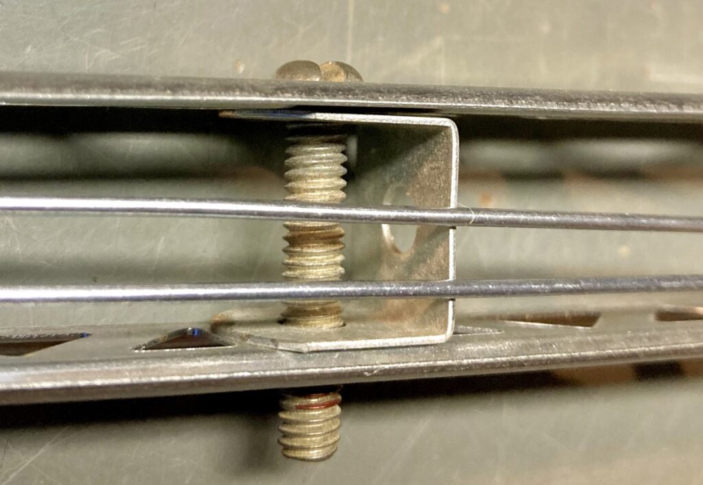
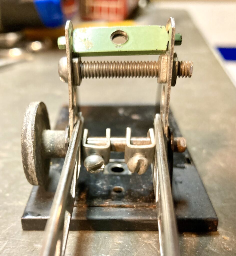
I have no plans to repaint or replace the wood underframe, as I’m aware of the previous owner, and leaving it is sort of a homage to him. Let’s just say I finished what he started. A few photos show details of the simple boom construction.
If you wish construct your own crane boom, here’s the Erector parts list I used:
- 2 each, “C” 10-inch girders
- 2 each, “F” 5-hole straps
- 2 each, “M” double angle brackets
- 1 each, “CH” right angle bracket
- 2 each, “P37” collar with screw
- 2 each, “S62” 7/8” x 8-32 bolts (one trimmed to 5/8”, one cut to 11/16”)
- 1 each, “S57” 1-3/8” x 8-32 bolt (trimmed to 1-1/16”)
- 8 each, “N21” nuts
Three items were reused from the original crane boom:
- AF part # “PA9219” hook block for crane
- sheave from the boom tip
- part the boom-height adjustment screw is threaded into (small flat part with a threaded hole in the center).
Other non-Gilbert parts were the two tension rods, made from 12-inch lengths of 18-gauge galvanized steel wire. The tension rods were bent to simply hook over the bolt at the boom tip. The other end of the wire was bent to hook into the upper holes of the upright 5-hole straps installed at the boom’s base. The wire was bought at a home improvement store. The string was replaced with a longer length of cord. I used a blue colored 1/8-inch cord found at a craft store.
If you wish to duplicate the shorter underframe, the dimensions are 5” long, 1-15/16” wide, by 3/8” thick. You could use wood, layered styrene sheets, or you have the means, aluminum or steel. Three holes will be required to be drilled along the centerline, required to mount the two trucks and the crane house assembly. Other underframe details are your choice.
Due to the added weight of the longer crane boom, I found it needed rear counterweight. On removing the cab, I placed old radio speaker magnets on the inside rear of the crane cab, but glued lead weights or stacked steel washers could do the same.
Also because of its heavier weight and long boom length, the crane will not track well in a train, so it’s destined to be placed on the layout as an interesting static display, perhaps the focal point of a scrap yard scene.
No doubt the engineers with Gilbert developed many items like this by tinkering around with the parts they had on hand. I’d say most of those tinkering’s were never seen outside the New Haven factory building and now lost to history. The intent in this project was to have a little fun and follow their lead.
Ben Swope
—————————
September 7, 2021
Fun with Gilbert models by Ben Swope
As Gilbert developed their HO scale line of model trains, many of the long-established S-gauge railroad road names were duplicated in their HO scale offerings. One must wonder what was the reasoning for the duplication. Was it the thought of S-gaugers converting to HO scale would want the same road names in the smaller version? Or was it simply easier and cheaper for Gilbert to reproduce these road names in HO scale?
A few HO scale cars however were manufactured with road names never offered in S-gauge. One was the #33509 Western Maryland piggyback flatcar equipped with a single RISS truck trailer. The trailer’s road name was also new to the Gilbert line, printed on the same trailer chassis used for the S-gauge line, always being much closer to HO scale than S scale.
I located a RISS truck trailer at a recent flee market, being the only Gilbert product in the box of other toy and model trains. Knowing this was somewhat of rare find, I of course snapped it up.
As an active S-gauger, my immediate thought was to create an S-gauge model of this #33509 HO scale railcar: sort of reverse modeling of the Gilbert line, while adding a new railcar to my S-gauge fleet with an authentic “prototype”.
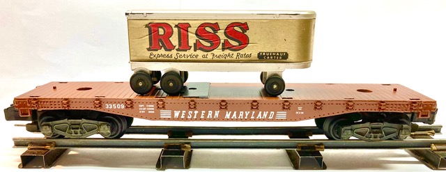
In reality, the Western Maryland Railway did use 50-foot flatcars to transport single truck trailers, similar to what Gilbert had offered, so duplicating this railcar with its lone trailer load in S-gauge made plenty of sense.
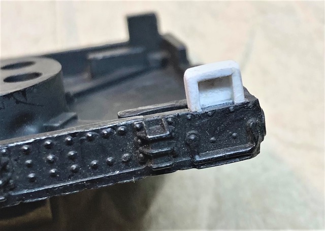
A common plastic S-gauge flatcar was retrieved from my parts box, being there for having several issues. Two of the four corner steps were broken off, and one truck was badly damaged, but overall, the car was a good candidate for repair and repainting into the Western Maryland road name.
After removing both trucks from the flatcar, the two missing corner steps were reconstructed with bits of .040 styrene sheet stock. Three sides of the small pieces of styrene sheet were overlayed with square .040 styrene stock, making the new corner steps in the same .080 thickness as the original molded-on steps. Once cemented to the car body, the square edges of the new steps were sanded to match the appearance of the original steps, and after painting, it is hard to tell these were replacements.
Next was preparation for paining, starting with a good washing to remove years of dirt and dust. Once dry, this was followed with several light coats of oxide red paint from a simple spray can, being a common dark red enamel primer.
Being also an HO scale modeler of the Western Maryland Railway, I had an assortment of WM decals to choose from and sized to best fit the S-gauge flatcar body. The same HO catalog number of 33509 was duplicated. Once painting and decaling was completed, an over-spray with semi-gloss clear paint sealed the decals. And once all was dry, the trucks were installed with new rivets.
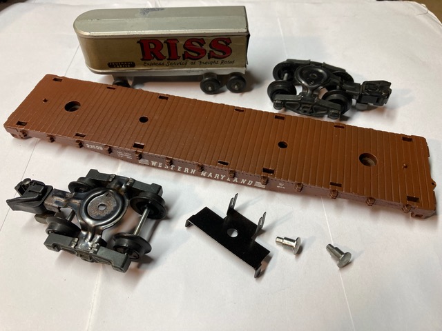
Finally, an S-gauge reproduction metal clip was installed to attach the piggyback trailer to flatcar, finishing the project. The result was a good-looking S-gauge model of a HO scale railcar using all Gilbert parts.
____________________________________
November 18, 2020
Something old is new again by Ben Swope
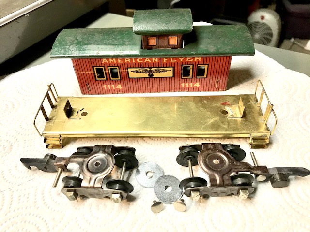
An old American Flyer tinplate caboose shell was purchased at a local train show. The old caboose dated to the Chicago Flyer O-gauge era, numbered 1114. Though it was missing its frame and trucks, with the name American Flyer emblazoned across the car body’s sides, I couldn’t resist the challenge to bring this old car back to life.
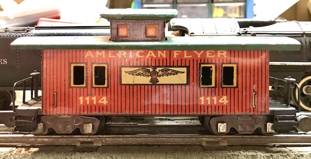
On examining the caboose shell on the workbench, I found the car’s width was just right for S-gauge, but a bit tall compared to other S-gauge equipment. A quick look online at some old wood caboose images found some strange and tall cupola designs. This was enough for me, and I decided my five-dollar investment was worth the time and effort to turn something old into something new again.
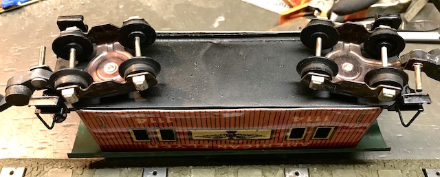
The biggest hurtle was to fabricate an entire new frame to carry the old caboose shell. I wanted to follow similar construction methods of the earlier tinplate era, so brass sheet, rods and angles were the materials used. In keeping with the earlier era, S-gauge trucks with link couplers were also chosen.
My home shop is limited in fabricating equipment, having no metal brake, punch press or spot-welding equipment, as the original manufacture would have had at their disposal when they first constructed this caboose. However, with some careful preplanning and with the aid of some steel straightedges, I was able to cut and bend the main frame piece to recreate the caboose frame, maintaining rigidity and the correct clearances needed to negotiate our tightly curved S-gauge Flyer track.
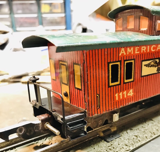
Without a spot-welder, the brass material allowed me to solder the pieces together. In assembling the four end steps, care had to be made to not unsolder what was first applied as the second piece was added, and then finally attach the steps to the car frame. Steel clothespin-type clamps and wet rags used as heat sinks turned out to be the trick.
I kept the end railings simple in design, as I was ‘modeling’ a toy railroad car here, again, attempting to follow the lead the original manufacture would have done.
The caboose shell was attached to the frame using brass angles soldered atop the frame just inside the car body ends, tapped to receive a #2-56 screw. Corresponding clearance holes drilled into the lower car ends allowed a screw on each end to secure the body to the frame.
Steel fender washers (extra wide flat washers) were used to raise the frame off the trucks and were just the right thickness to use common American Flyer truck rivets to attach the trucks after painting.
With most of the frame assembly complete, it was washed, primed, and spray painted black. After the paint dried, two small metal handbrake wheels were gleaned off retired AF caboose end railings. The brake wheels were dropped onto the attached vertical brake staffs, secured by deforming the top protruding end of the staff.
With the brake wheels mounted, the car body was set on and secured with the two screws, completing the final assembly. This ‘new’ old caboose was now ready to protect the rear of the next freight train leaving the rail yard.
I hope this brief description of making an old toy train car new again is an inspiration to look under the tables at train shows, seeking unique projects to keep this hobby vibrant and interesting.
End of Something old is new again by Ben Swope
____________________________________
August 15, 2015
American Flyer Railcar Loads by Ben Swope
From the first day an American Flyer train set was unpacked, perhaps on a Christmas morning, flat cars and gondolas were subject to having custom loads inserted. Likely loads inserted by children, were perhaps toy cars, marbles or maybe army men. Basically, anything small enough to fit in or on the car, and handy enough to represent a railroad car load, at least in a kid’s mind. As an adult, our sense of scale and practicability rule out the child-like loads of marbles and army men to more sophisticated tastes of better scaled loads and something more in tune to what a railroad might actually haul. In this short series we’ll be looking at a few loads I have created, and how they were placed onto AF cars in a manner American Flyer would have done from the factory. These loads may not be totally true 3/16” scale or use prototype railroad securement methods. The guys at American Flyer took liberties with scale and securement to engineer “play value” into these loads – my aim was to follow their lead. In this first installment we be looking at three simple loads, all using American Flyer items in a different way to create believable “American Flyer” car loads.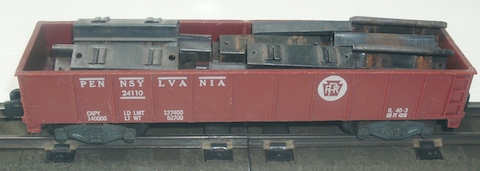
First is a simple gondola car load. This load could be called either a scrap metal load or a work train car load. This load consists of retired AF cross ties gleaned from old track sections. Simply pry open the tabs that hold the rails in place, remove the rails and the fiber insulation the cross-tie, and flatten out the tabs. The car shown has about 20 ties in it. This number of ties does not make the car too heavy, fills it to the top, and can be loaded or off-loaded with a crane magnet.
If you are a collector of AF items, you are bound to have retired rail cars or accessories that are kept for their parts. This next car is a flatcar loaded with a crane boom assembly. These booms were widely used through the AF line for early wrecking cranes, the magnetic crane and even used on an early station platform. Having an extra crane boon in my parts bin, I placed on a flatcar and noticed this could have been something American Flyer could have easily done from the factory. To secure the boom to the flatcar (here using a die cast car) I cut strips of sheet tin to the match the width of the flatcar floor slots (about 3/16”), bending the strips around the boom and threaded the ends through the floor slots. Once satisfied the load would be securely attached to the car, I cut the strips to length and folded ends tightly to the underside of the car.
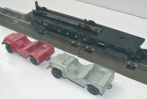
The third load in this installment started with an auction purchase of a bunch of AF items. In the box purchased was a 25515 U.S.A.F. flatcar. Missing was the motorized rocket sled, but the bracket to hold the sled was in-place. Acquiring a rocket sled could be costly, so a search for something appropriate for an Air Force flatcar was on. The brackets have slots intended to hold the rocket sled’s axles (likely the same bracket to hold trailers for the 24550 Monon piggyback flatcar), and will readily hold other axles.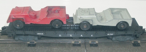
Painting a pair of American Flyer piggyback trailers to U.S.A.F. was considered. But a more likely load of Air Force Jeeps would be more believable. I had two Tootsie Toy on hand, and these seem to fit the bracket well. The bracket was left unmodified, including the tall tab at one end (that nestles nicely in the Jeep’s engine compartment area), as someday I may locate a rocket sled.
The Jeeps shown will be painted or replaced with others (with matching wheels), perhaps painted with Air Force blue color. Tootsie Toy (and others) have made over the years all sorts of armed forces wheeled pieces that may fit this car even better.
But, for the purpose of this article, you can see what can be done with a little thought, little money, and a bit of imagination.
End of Part 1 – Ben Swope
________________________________________
September 30, 2015
American Flyer Railcar Loads Part 2 by Ben Swope
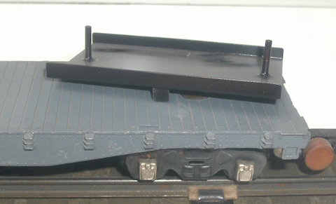
In this second installment on creating American Flyer railcar loads, we will be loading some S scale farm tractors. Farm machinery loaded on flatcars was, and still is, a common way to transport these colorful machines long distances.
Several models of inexpensive S scale die cast tractors are available from Ertl. I bought mine at a local Tractor Supply Company (TSC) store. There are several models to choose from, they cover several eras, making it easy to find a model to match either the classic 1950’s era of American Flyer, or if you prefer a more modern era.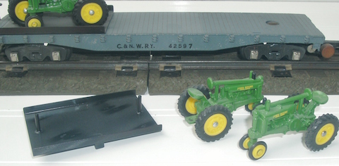
Start with by placing the tractors of your choice on the flatcar, deciding how many and the way they will fit the car deck. The tractors I chose were a “tricycle” type, having a narrow spacing of the front tires. Tractors of this type were frequently loaded nested at an angle to fit as many on the flatcar deck as possible. Though I only used four tractors, I still loaded them at an angle for the nested look.
We will be using sheet brass as a tray to contain these tractors aboard an AF flatcars. The car I chose for my tractor load was a die cast flatcar, but the same methods allow for placement on an AF plastic bodied flat.
The tractors get placed on a tray made of sheet brass, and will have attached tabs or keys, to drop into slots in the flatcar deck to secure the load. I used a brass sheet thickness I had on hand for this project; .015”, or 26 gauge. Choose a thickness that allows you to easily bend angles along two edges.
Using the tractors as a guide, I determined how long to make each tray (with my two tractors sitting nested side by side). The width is determined by the flatcar width or just wide enough to comfortably fit your tractors in the way you wish to load them, plus the added width of the folded up edges to contain the tractors.
Bend the side edges up to give you about 1/8-inch lip. This does two things, it contains the tractors and it adds strength to the tray. Next decide where on the flatcar to place the tray(s) and where to key the tray to slots within the flatcar deck. I used a pencil to mark the location through the underside of the flatcar deck slot while holding everything in alignment.
Once the location for the tray to flatcar key is determined, cut a slot from the underside in the tray with a Dremel tool using a reinforced cutting disk (use care and eye protection). Next, cut some brass angles to length matching the slot in the flatcar deck and the slots cut in the tray. Clean, flux and solder the angles through the top of the tray positioned where the tray is snug in the slots and so the tray rests flat onto the deck.
Next, I used 3/32-inch brass tubing soldered to the tray in a vertical position (as posts) and set the rear hitch of the tractor over the tubing. Doing so, it’s easy to load, unload, and swap-out tractors (say from green to red tractors).
The final thing to do is to de-bur all the edges and corners, clean and paint the tray(s). I chose a black color, as AF would have done if the fellows at Gilbert would have done this same project.
End of Part 2 – Ben Swope
____________________________
November 12, 2015
American Flyer Railcar Loads Part 3 by Ben Swope
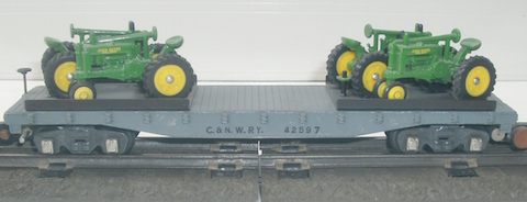
For this final installment we will be loading a Tootsie Toy road grader. Other brands of road graders, other construction machinery or even military loads could also use this method. I happen to have a Tootsie Toy grader on hand and liked the way it looked sitting on a flatcar (granted, it is a bit oversized). Besides any shortcomings, this is something the guys at American Flyer could have done.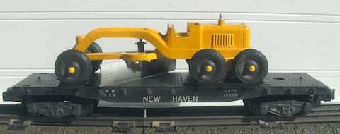
I found the grader’s wheel spacing was too wide to properly sit on a common AF plastic body flatcar. So an extended platform is required to contain the wheels. This platform will double as the grader’s wheel chocks and keep it secure to the car as it travels over your pike.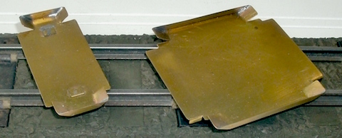
My platform was made from simple 0.10” brass sheet stock, obtained at a local hobby shop (K&S was the brand used and was easy to find). Two platforms were required, one for the front tires, and one slightly larger for the two-axle set of rear wheels of the grader.
Utilizing the factory molded holes and slots in the flatcar deck, I located three pairs of slots that the platforms could key into to keep the load centered and contained to the car. The engineering of the platform’s dimensions took these slots into consideration.
The length of the platform (front to back direction of the machine) was dictated by the size of the grader’s tires. The extreme outer edges of the wheel tread was the length of the platform. If the wheel is ¾ inch in diameter, make the platform length ¾ inch.
The width was made 1/4 inch wider than the outsides of the tires mounted on the grader’s axles (the width being the side to side direction of the machine). This extra width allows for the 1/8 inch on each side to be folded upwards to contain the wheels in a side to side motion.
Once this was done, make two cuts with shears near the four corners of the platform, and bend the brass upwards to form wheel chocks, limiting the wheels front-back motion. Soldered these chocks to the folded sides, making sort of a shallow pan the axle assemblies snugly sets into.
Once these steps were done, place the platforms with the road grader inserted atop the flatcar. Locate the molded slots in the flatcar deck were best to install downward tabs to key the platforms to the car.
The tabs created for the front axle were small pieces of brass angle stock. Dropping one leg of the brass angle through the platform slot leaves the bottom surface of the platform flat to sit on the flatcar without teetering.
The four rear platform tabs were simply cut and bent from the platform’s flat base, keying into two other pairs of flatcar slots.
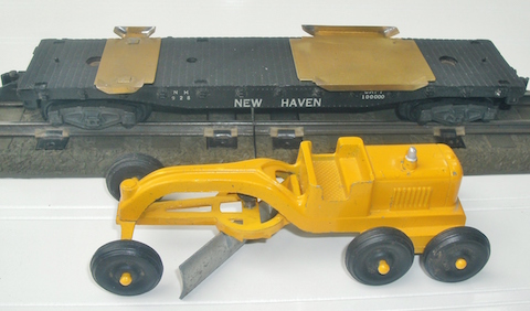
After being satisfied with the assembly and fit of the load and to the flatcar, de-bur all the platform’s sharp edges with a file and sandpaper and wash with hot water and soap. Once dry, I painted it black. The black color paint matches the flatcar and allows the platform to disappear under the machine’s black wheels and yellow painted load.
Tootsie Toy road graders are a bit wide, but railroads haul high & wide loads quite often – so this is still a prototypical load. However if replicating this or other wide loads, you’ll want to check for proper clearance with your load for close clearances on your curved tracks, through tunnel portals and past the AF turnout switch housings.
This has been the third and final part of the AF Railcar Load series. I hope that you have enjoyed it.
End of Part 3 – Ben Swope
________________________________
May 5, 2015
AF Steam Engine Tester by Ben Swope
Many American Flyer S Gauge hobbyists enjoy restoring their vintage equipment. For me, restoring these old worn items back into their original operating condition has always been one of my favorite parts of the hobby. Let’s look at a homemade tool used to assist servicing American Flyer steam engines, and how with a little effort and a few simple parts, you can construct your own.
Several drawings, both in-print and on-line, have shown the standard 4-wire connection of AF steam engine’s rear of cab electrical jack panel; where to place a jumper wire on the panel, and where to apply the power leads when the engine is not connected to the tender and its reversing “E-unit”.
One on-line resource Port Lines displays some very nice wire schematics of the standard 4-wire and the 5-wire engine/tender connections, along with the other 2-wire type tender connections; each noting the jack panel wire locations leading to the various connections on the engine drive motor, smoke and headlight connections, and the tender and reverser wire connection points.
After a search for information on how to create a four or five-wire steam engine test wire harness; one that attached directly to the engine’s jack panel, none could be found. So I created on my own.
Ben’s Test Wire Harness for American Flyer Steam Engines
The accompanying drawings show first, a 4-wire test lead utilizing a simple double-pole-double-throw (DPDT), center-off toggle switch to create a forward/off/reverse option.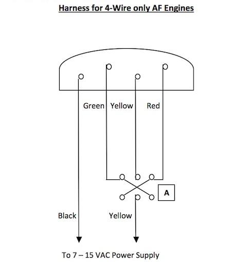
Switch “A”: The motor direction switch, being a double-pole double-throw, center-off switch. This switch performs the same function as the tender mounted reverser.
The next drawing adds a second DPDT switch to the circuit, making it switchable from a four to five-wire engine/tender wiring design. An optional on/off switch may be used to make a connection to the smoke unit and headlight for engines with the 5th tender wire connection.
Switch “A”: The motor direction switch, being a double-pole double-throw, center-off switch. This switch performs the same function as the tender mounted reverser.
Switch “B”: Also a double-pole double-throw; used to compensate for the difference in the 4-wire to 5-wire connections to the motor brushes/field coil.
Switch “C”: Optional single-pole on/off switch; connecting the smoke unit/headlight to the power source through the direction switch.
The four wires to the jack panel were soldered to a salvaged male plug off an unused tender chassis.
The 5th wire for the smoke/headlight connection may be connected to the engine by using a small covered alligator clip or similar device. On my engines, this 5th wire connection typically is converted from a factory soldered connection to a homemade 1/16-inch jack plug and socket using brass tubing; thus for servicing, the tender can be easily and totally disconnected from the steam engine.
This wire harness assembly will allow you to leave the test leads attached during servicing work. And it comes in handy when the engine is turned upside down, as an attached tender’s reverser will not work in this inverted position.
In all, this is a rather simple electrical circuit (if I can figure it out – it’s got to be simple), with all of the components coming out of my parts box. I used colored wire, but any color of flexible light-gauge stranded wire would work. I found the color and polarity of the two power lead wires doesn’t matter if you’re using AC current.
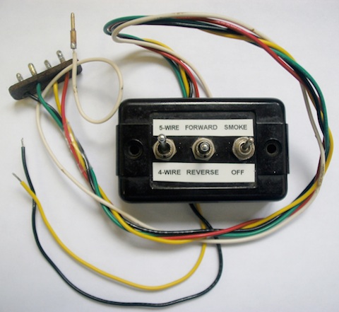
To keep things neat and flexible in use, I braded the wires from the switches to the male plug, and slipped on a bit of heat-shrink tubing before soldering the final wires into place, but tape could do the same. The toggle switches used were of the tiny sub-miniature type. These toggle switches were small enough to mount all three into an old style empty AF control box; and would be handy if you wanted to mount the control box to your workbench.
This harness, by isolating the tender from the engine, may aid in diagnosing an electrical problem. For example, if the engine runs fine on the harness, and not when connected to the tender, obviously the tender has an issue.
Also, do not attempt to operate a 4-wire engine on the 5-wire switch setting (or visa-versa), as the resulting electrical short may damage the engine or power source. Labeling your switches will help avoid this situation.
The bit of work to assemble this test wire harness assembly may save time and hassle on your next steam engine service work. And best of all, it cost just a few dollars to make.
Ben Swo
Many American Flyer S Gauge hobbyists enjoy restoring their vintage equipment. For me, restoring these old worn items back into their original operating condition has always been one of my favorite parts of the hobby. Let’s look at a homemade tool used to assist servicing American Flyer steam engines, and how with a little effort and a few simple parts, you can construct your own.
Several drawings, both in-print and on-line, have shown the standard 4-wire connection of AF steam engine’s rear of cab electrical jack panel; where to place a jumper wire on the panel, and where to apply the power leads when the engine is not connected to the tender and its reversing “E-unit”.
One on-line resource Port Lines displays some very nice wire schematics of the standard 4-wire and the 5-wire engine/tender connections, along with the other 2-wire type tender connections; each noting the jack panel wire locations leading to the various connections on the engine drive motor, smoke and headlight connections, and the tender and reverser wire connection points.
After a search for information on how to create a four or five-wire steam engine test wire harness; one that attached directly to the engine’s jack panel, none could be found. So I created on my own.
Ben’s Test Wire Harness for American Flyer Steam Engines
The accompanying drawings show first, a 4-wire test lead utilizing a simple double-pole-double-throw (DPDT), center-off toggle switch to create a forward/off/reverse option.
Switch “A”: The motor direction switch, being a double-pole double-throw, center-off switch. This switch performs the same function as the tender mounted reverser.
The next drawing adds a second DPDT switch to the circuit, making it switchable from a four to five-wire engine/tender wiring design. An optional on/off switch may be used to make a connection to the smoke unit and headlight for engines with the 5th tender wire connection.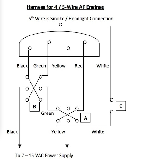
Switch “A”: The motor direction switch, being a double-pole double-throw, center-off switch. This switch performs the same function as the tender mounted reverser.
Switch “B”: Also a double-pole double-throw; used to compensate for the difference in the 4-wire to 5-wire connections to the motor brushes/field coil.
Switch “C”: Optional single-pole on/off switch; connecting the smoke unit/headlight to the power source through the direction switch.
The four wires to the jack panel were soldered to a salvaged male plug off an unused tender chassis.
The 5th wire for the smoke/headlight connection may be connected to the engine by using a small covered alligator clip or similar device. On my engines, this 5th wire connection typically is converted from a factory soldered connection to a homemade 1/16-inch jack plug and socket using brass tubing; thus for servicing, the tender can be easily and totally disconnected from the steam engine.
This wire harness assembly will allow you to leave the test leads attached during servicing work. And it comes in handy when the engine is turned upside down, as an attached tender’s reverser will not work in this inverted position.
In all, this is a rather simple electrical circuit (if I can figure it out – it’s got to be simple), with all of the components coming out of my parts box. I used colored wire, but any color of flexible light-gauge stranded wire would work. I found the color and polarity of the two power lead wires doesn’t matter if you’re using AC current.
To keep things neat and flexible in use, I braded the wires from the switches to the male plug, and slipped on a bit of heat-shrink tubing before soldering the final wires into place, but tape could do the same. The toggle switches used were of the tiny sub-miniature type. These toggle switches were small enough to mount all three into an old style empty AF control box; and would be handy if you wanted to mount the control box to your workbench.
This harness, by isolating the tender from the engine, may aid in diagnosing an electrical problem. For example, if the engine runs fine on the harness, and not when connected to the tender, obviously the tender has an issue.
Also, do not attempt to operate a 4-wire engine on the 5-wire switch setting (or visa-versa), as the resulting electrical short may damage the engine or power source. Labeling your switches will help avoid this situation.
The bit of work to assemble this test wire harness assembly may save time and hassle on your next steam engine service work. And best of all, it cost just a few dollars to make.
Ben Swope
_____________________________
April 11, 2015
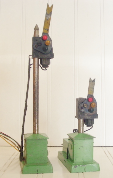
Making a AF Dwarf Signal by Ben Swope
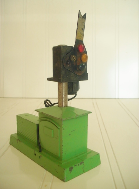
As intending to signal a large single track loop for multiple train operation, I wanted to keep the layout pure American Flyer, so the obvious choice is to use AF’s # 761 semaphores. To keep the six signaled controlled blocks at an even length, one signal is required to be placed in a long hidden section under benchwork. Here the overhead restriction would be too low for these tall semaphore signals, standing 9-inches tall with the blade in the “clear” position.
The solution to this problem came in the form of a train show junk box find, were a # 761 semaphore was purchased so cheaply, experiments could be made without concern if the signal was destroyed in the process. However the first attempt at modification resulted in such a success, I thought other AF enthusiasts would be interested, and perhaps offer another signal option for use on your own pike.
This junk box purchased operate quite well, though it was not in perfect appearance, and had a few parts missing. This made it a good candidate to convert to a dwarf signal, yet once modified would operate identical to standard versions.
Start the modification by removing the semaphore blade, ladder, bulb socket, finial from atop the mast, and the coil & blade activation rod assembly from the base. At this point all you’ll have is the base casting, the signal head casting, both connected only by the hollow mast tube.
Using a small punch and hammer, carefully drive the mast tube out of the base from inside of the base casting. Work the punch around the tube’s end to avoid cocking the tube within the casting, as damage the base structure may result.
Once removed, measure and mark the mast tube 1-inch from the bottom of the signal head and cut the mast tube off squarely (I used a common hacksaw). De-burr and true-up the ragged cut to prepare resetting it back into the base casting. If done correctly, a few taps on the top of the signal head (using a block of wood to protect the signal head casting from the hammer blows) will set the mast back into the base casting. If necessary, some glue may be used to secure this connection. Ensure the signal head is located in its original orientation to the base.
This process should make the now exposed distance from the mast tube of the base structure to the bottom of the signal head about ¾-inch. This is about as short you’d want to allow for easy removal/insertion of the bulb and socket assembly.
Next is the activation rod modification (the rod that rides inside the tube). Place the coil and activation rod assembly back into the base and fasten with the original screws. Of course, this rod will now extend far out the top of the mast and signal head at this point. Push and pull the rod to its extreme motions while sighting through the signal head. Observe the rod’s end movements though this crescent shaped hole and mark its end strokes with a small felt-tip marker.
Remove the coil and rod assembly again. Note the marks on the rod and find the middle of the extreme motion marks. Remark this point with a different color marker (or score with a file, etc.), and replace the assembly to check the center marked point prior to drilling. Pear again in the signal head hole to double check its location as being the best point to drill a new hole for the signal blade pin hole and thus rotate the signal blade correctly.
Once satisfied of the location, remove the coil/rod assembly once more and drill a new hole sized for the pin that rotates the blade and de-burr. Follow this by cutting the rod to length just above the newly drilled hole and de-burr.
For my dwarf signal, I chose to shorten the signal blade as well; removing about ¼-inch off the fish-tailed end. At this point, it’s your choice to make this cut flush, recreate a fish-tail end or simply not shorten the blade.
Lastly, I chose not to replace the finial atop the signal head (as with a shortened signal blade, it looked too “busy”). I instead modified an old AF freight car truck rivet, and with contact cement, placed it in the same hole the filial once was, acting as a button cap to keep dust out.
This signal, once reduced in height, looks to have been an item Gilbert would have produced and advertised as a working dwarf signal, perhaps used in conjunction with power switches at the end of a passing siding, branch line junction or yard lead.
This entire modification took about two hours to figure out and perform. With these simple instructions, your time may be less. If you choose to do the same, your efforts will yield an interesting new addition to the many American Flyer accessories on your layout.
Ben Swope