August 28, 2014
Stumpy’s Station – “Ten Wheeler Project” Part 1
One locomotive that I have always wanted in S gauge is the 4-6-0, known as a “Ten Wheeler” because it had six drivers and a four wheel lead truck. As a direct “upgrade” of the common 4-4-0 “American,” the 4-6-0 wheel arrangement gave the superior high speed tracking of the “American” with the four wheel lead or pilot truck to help turn the locomotive, and the tractive effort of six driving wheels. Most “Ten Wheelers” had as big a boiler as the technology of the time and the space available could provide.
Most railroads used 4-6-0’s interchangeably for both passenger and higher speed freight traffic. In later years, these locos avoided scrapping by being downgraded to lesser assignments such as local freight and passenger trains, work trains, and even switching duties. Many 4-6-0 locos could still be found in daily operation to the end of steam on the mainline railroads because they were easy to maintain, and light weight enough to work on the lightly laid rail and light bridges found on branch lines. Short lines and tourist lines loved smaller locomotives like them for the same reasons.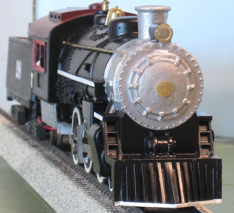
Of course American Flyer never made a 4-6-0. But during the sixties and seventies when S scale guys had little to work with aside from old Flyer, a LOT of custom rebuilt locos appeared and the “Ten Wheeler” was one of them. Generally, these were made from Atlantics by a bit of modifying of the frame and adding a third set of drivers where the trailing truck would be.
A few guys used the Pacific because all you had to do to get the 4-6-0 wheel arrangement was remove the trailing truck. The problem was to somehow cover the long gap under the firebox/cab area or disguise the motor sticking out of the back of the cab in full view of anyone. Few got it right.
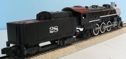
I’ve been giving this project some thought for years, and this series will follow my “Ten Wheeler Project” kit bash of a common Flyer plastic Pacific into a 4-6-0.
The biggest problem with this kit bash is to do something about covering up the motor while at the same time shortening the shell enough to look fairly realistic. The only actual chassis work will be taking the trailing truck off and making a longer drawbar to connect the tender. As usual, I made a new drawbar out of craft (popsicle) sticks because they’re durable, an electrical insulator, and easy to work with.
As part of this conversion, I decided to back date the Pacific shell to look like a typical early Twentieth Century loco that had been updated from time to time and worked right up to the end of steam. There are two ways to do this: buy brass castings of various parts, or cut up an old Flyer “Casey Jones” shell.
Castings can quickly become expensive, while a common “Casey Jones” can be had complete and running for about fifteen dollars, a bare shell for one might go for five dollars. You can’t buy detail parts for prices like that!
The Pacific used for most kit bash projects can be pretty scruffy looking because it’s going to get some cosmetic work anyway, just be sure the mounting posts are in good shape. You might consider buying a Pacific shell for customizing if you have a nice Pacific on hand, and you can swap the customized shell onto your nice loco’s chassis.
Another consideration is the tender. A Franklin tender would be perfect to help back date this project. The tender from behind the 0-8-0 would make a nice slightly more modern choice. You also might consider a Marx or even “027” Lionel tender shell on a Flyer tender chassis. In some cases you may have to shorten the chassis to make this work. Yet another option is to get a common Flyer plastic tender (use the one from the “Casey Jones” you buy for the boiler shell) and cut the fuel bunker sides off even with the top of the tender tank. Add a sheet of plastic to cover the remaining hole and build a coal box on top to get that older tender look.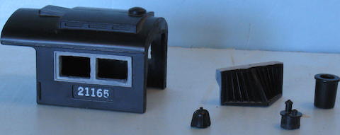
Once you’ve decided what you want to do and gathered the various tid-bits, it’s time to start. I began by salvaging parts from the “Casey Jones” loco shell. Using a Dremel motor tool with a cutting wheel (a hobby saw works well but is just slower,) I cut off the cab, stack, bell, safety valve turret, headlight, and pilot (“cow catcher.”) I also removed the two domes by cutting into the shell rather than cutting the domes. This gives you extra material to work with for this and other possible projects. After all, once you remove the cab, the rest of the shell is pretty much scrap anyway. I keep a number of parts and “junk” boxes for possible future use and therefore a project is less often stalled for lack of parts.
We’ll be using the cab in this project, and one of the ugly things about the “Casey Jones” is solid cab windows. These can be opened up by drilling a series of small holes all around the inside of the windows and then cutting between them to remover the plastic. Dress the windows up with a file.
Next time, we really get started with the project.
End of Part 1 – Stumpy Stone
______________________________
October 2, 2014
Stumpy’s Station – “Ten Wheeler Project” Part 2
We’ve run the “Casey Jones” shell “through the scrap line” and salvaged useful parts. Now it’s time to make few serious cuts to the plastic Pacific shell.
For the major cuts, I use a Dremel Motor Tool with the cut off wheel and then go back and dress up the cuts with a file. Filing to final form allows you better control to make sure parts are straight.
We’ll cut off the Pacific’s pilot (“cow catcher”) along the straight vertical line of the front of this part, the thickness of the front of the pilot, leaving the two wedged shaped area intact to help strengthen the replacement part. The pilot removed from the Casey Jones and the cut line of the Pacific shell should be filed to fit tightly. The pilot of the Casey Jones is a slightly narrower than the Pacific pilot deck, so carefully center the Casey Jones pilot when gluing. We take care of the excess deck on each side later.
The next cut is the important one. We’ll be cutting the cab and firebox of the Pacific away to make room for the Casey Jones cab. Turn the Pacific shell over and locate the rear chassis mounting posts. Mark a line just behind these all the way around the shell because this is where we’ll make the cut to remove the rear portion of the Pacific shell.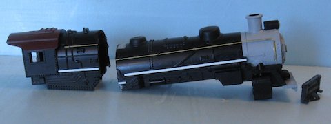
You can either cut right on the line, or a little rearward of it to give yourself extra material to work with if you need to. The plan here is for the Casey cab to just cover the back of the motor. There is a slight difference between using a can motor and an original Flyer motor so measure twice and cut once!
Once again, file the cut lines of both the Pacific shell and the Casey Jones cab to fit tightly. I like to use some gray primer in all areas where modifications are to be made since working marks will show up better, and the gray allows you to see how your “body work” is as you build better than the normal black plastic.
At this point I had to turn my attention to how high to mount the cab as well as make sure there was enough length to cover the motor. On an old Ten Wheeler, the stack, domes, headlight, and cab would sit well above the boiler. Those old locos had smaller diameter boilers than later engines so vertical clearances were not as important. However, in our case, we must build the locomotive to fit the S gauge clearances of tunnels and bridges.
In this case, I wanted the top of the stack to about the same or a little taller than the cab roof. I used the stack height I had used on the “Prairie Dog” project since that had been set to clearances for tunnels and bridges, so the stack would be ½” above the top of the boiler. While looking things over
during the planning this project, I decided to just go ahead and use the Prairie’s shell to build the Ten Wheeler! The Casey Jones stack is about a ½” tall anyway! This also let me skip the steps to make a stack and headlight during construction, but I’ll describe them here for you.
I cut the original headlight and stack off the plastic Pacific shell and filed these areas flat. The hole where the headlight was can be filled with plastic rod or wooden dowel and touched up with putty. I like to make a few punch outs of card stock with a paper punch, glue them together in a “stack” of punch outs, and then glue this to the front of the boiler to represent a number plate.
A new headlight will be mounted to the top front of the boiler, typical of older style locomotives. This headlight will be made of a piece of plastic tubing 5/16” inch outside diameter. Cut a round piece of plastic to fit the diameter of the new headlight and glue it on the “back” of the tubing.
Next, drill a 3/16” hole in the top of the boiler as far forward as you can. Then drill another 3/16” hole in the “bottom” of the headlight that aligns with the hole in the top of the boiler.
Leave the inside of the headlight white or paint it silver to reflect the light from the light bulb in the front of the engine. If you can, use the original Flyer headlight lens. A short length of clear plastic rod that fits inside the new headlight will also make a good lens, but a flat piece of plastic cut to fit the “front” of the headlight will work too. Do not install the lens until after the locomotive has been painted so you don’t accidentally get paint on it.
Once the headlight is installed, you can add the Casey Jones stack at it’s full length. This will be a simple and straightforward installation.
Since the bell will be moved, carefully pry the original metal bell out of it’s hole with a small screwdriver. The bell is just pressed in. Fill this hole with some putty.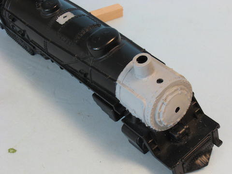
I wanted to use the Casey Jones safety valve turret to help back date the Ten Wheeler, so I filed off the three safety valves at the back top of the cab. This is where the Casey Jones turret will go. The Casey Jones bell will go right in front of the rearward dome. File the parts to fit tightly and attach.
End of Part 2 – Stumpy Stone
______________________________
November 2, 2014
Stumpy’s Station – “Ten Wheeler Project” Part 3
I wanted to use the Casey Jones pilot (cow catcher) on the front of the 4-6-0, so after some trimming and filing, I glued it to where the Pacifc pilot was removed. A couple of pieces of plastic strip filled in the ends.
The last thing that we’ll be fitting onto the modified plastic Pacific shell is the cab. Before doing this, cut the fake firebox area off the bottom of the cab since it won’t be used on this project. As we considered in the last part of the project, the top of the cab should not be higher than the stack. With the fake firebox gone from the cab, the bottom of the Pacific shell and the bottom of the cab will line up to put the cab at a nice height.
The opening in the front of the cab and the outside diameter of the boiler shell is close, but not the same. To make this connection point a bit stronger, I used a piece of plastic sheet glued to the front of the cab and cut out the inside of this sheet to closely match the boiler opening.
Test fit the cab to the back of the boiler before gluing them together.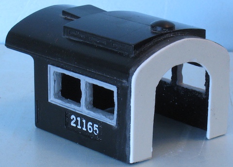
On engines without a trailing truck under the cab, as much space as possible was needed for the firebox. In many of the Ten Wheelers the firebox extended all the way to the back of the cab. This was know as a “deckless” cab because the engineer squeezed in between the side of the firebox and the inside wall of the cab with the fireman doing the same on the other side of the boiler, if he had time to sit down at all.
In our case, the Casey Jones cab has an enclosed rear bulkhead with narrow doors for the engineer and fireman. This was a rare style of “all weather cab” popular on many roads operating in cold climates, so we can use it. If the motor doesn’t clear the back of the cab, you can open the center area between the doors, as most deckless cab arrangements were hand fired from the front deck of the tender.
As an alternative, you could also open up the entire back of the cab to clear the motor and then use cab curtains to disguise the motor. Cab curtains were used in cooler weather to enclose the back of the standard cab type to keep the crew warm. These were made of heavy canvas, one on each side of the cab, and arranged on a slide so that they could be tied back at the sides of the cab while not in use or pulled around to enclose the open rear of the cab. I make these out of used dryer sheets glued together and cut to size, then painted an off white or tan color and use them to hide the back of the exposed motor. Install cab curtains (if used) after attaching the cab to the boiler.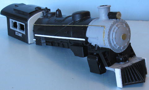
Once you’re satisfied by the fit, glue the cab to the boiler. Be careful to keep
everything in alignment, blocking everything into position while the glue sets. It’s a good idea to allow extra time for the glue to set as this is an important structural connection. Once set, I added extra strength by mixing up a little epoxy and spreading it liberally along the joint, then let that set overnight.
Once the cab is on, test fit the complete chassis and do any minor cuts or filing to adjust the fit. If there are any openings between boiler and cab, use some putty the fill these and then file and sand these areas smooth. As with our previous projects use gray primer to check your “body work,” then sand and repaint as necessary.
As I said before, many of the Ten Wheelers had a deckles cab because the firebox extended to the back of the cab. To help disguise the gap between the back of the drivers and the end of the cab, we’ll add this firebox under the cab. I started by adding a piece of plastic strip ¼” wide by 2 1/4” long to the bottom of the cab on each side, front to back. To this I glued a piece of 1/8” wide plastic channel material along the edge closest to the opening under the cab. Once the glue sets I used a ½” wide by 1 7/8” long plastic strip standing on edge to go below the bottom of the cab to block side view of the motor. This makes a “L” shape under the cab on either side. I left the front and back open for clearance when installing the chassis to the shell and to allow wiring to exit below the cab. It will also not interfere with the drawbar to the tender.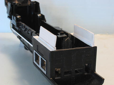
A firebox has hundreds of rivet heads appearing on it, so the represent these, I used card stock with “rivets” rolled on with a Ponce wheel. Ponce wheels are hand held tools used in sewing and other craft work. They consist of a small handle with wheel at the end that looks like a tiny saw blade. You place a piece of 1/2”x 1 7/8” card stock on a soft surface such as sheet balsa, rubber, or soft plastic. Then you roll the Ponce wheel along the card stock lengthwise making about four straight lines 1/8” apart. When done, turn the card stock over and you have lines of “rivet heads” sticking out on the other side!
Make a second such sheet for the other side and glue each to the ½” x1 7/8” plastic firebox structure. This makes for an easy and inexpensive firebox under the Ten Wheeler’s cab. When the glue is dry give this a light coat of gray primer.
With the boiler modifications complete, we’ll move on the adding a tender.
End of Part 3- Stumpy Stone
______________________________
December 5, 2014
Stumpy’s Station – “Ten Wheeler Project” Part 4
With the boiler shell/cab construction complete, we need to add a tender before running the loco through the paint shop. Probably the best tender to use to back date this engine to the “Turn of the Century” look would be the American Flyer “Franklin” tender. About the only thing you need to do with one of these is to add a coal pile in the opening left when you remove the wood pile. Many locos of the Nineteenth Century had short, low sided tenders, somewhat like the common 4-4-0 tenders. However, Franklin tenders are often hard to find.
The next “oldest looking” American Flyer tender is the one from the 0-8-0 switcher. You might want to remove the back up light, as these didn’t become common until the Twenties, but it’s not really necessary because your Ten Wheeler could have been “upgraded” during it’s years on your railroad. But again, these are hard to come by.
Next in line to give and old look are tenders from some of the cheaper Marx steamers or Lionel “027” steam locos. Look for the ones with the squared coal bunker like the Flyer 0-8-0 tender. Lower cost Marx and Lionel engines had these and they are cheap when you find them. Often you can just buy the shell, which is all you really want anyway.
This shell can be fitted to the Pacific or Casey Jones tender frame by cutting the tender chassis in half and shortening it to fit under the shell. As an alternative, you can make a floor/chassis out of plastic or wood and use American Models or S-Helper/MTH tender trucks and coupler. Just remember the tender weight must be used on any tender for good tracking and to help with electrical pick up.
The last alternative for a tender in the more modern American Flyer common plastic tender. This could be used as is to represent a later tender use dto give the Ten Wheeler added range. (This WAS done as water towers were removed toward the end of steam operations, and some small locomotives pulled tenders as long as the locomotive!) You could also back date the common tender by cutting off the fuel bunker above the main body, adding a deck of plastic sheet and building a coal box on top (it would be made to look like the 0-8-0 tender, only longer.) Shortening the tender would back date the look as well.
In the case of my Ten Wheeler, I used the Marx tender already on hand from the “Prairie Dog”.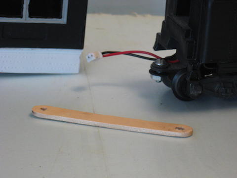
Once you have the tender ready that you want to use, it’s time to make up a drawbar to connect the Ten Wheeler locomotive to it’s tender. I’ve had good success using craft sticks for drawbars. They are remarkably durable in use, electrically insulated, cheap, and easy to work.
Since there is no trailing truck to work around, making a drawbar is very straightforward and simple. Measure the distance between the trailing truck screw and the front screw/rivet hole of the tender drawbar. Mark where your screw holes have to go on the craft stick to connect the trailing truck screw and the rivet/bolt hole in the tender or tender drawbar, depending on which tender you’re using.
Because the craft stick wood is very hard, drill the holes and THEN cut the craft stick beyond them. This eliminates any splitting of the wood that some times happens by drilling too close to the end of a stick. Use a file to round off the ends of the new drawbar and paint it black. Test fit and you’re ready to “couple up!”
The final step is to test run the finished loco and work out any problems. Once everything is working correctly, the locomotive and tender go to your paint shop. Even though I started with the “Prairie Dog,” I sanded and primered the loco again. Then I painted the boiler and cab black. The cab roof and tender rear deck were painted boxcar red.
The smokebox and firebox were painted silver to represent a fresh coat of graphite. (Graphite was used on areas not covered by asbestos and jacketing where the high heat would burn paint off quickly.)
The bell and parts of the safety valves were painted gold to represent brass, and so were the handrails on the boiler and the grab irons on either side of the cab. As was popular in the old days, I painted the window frames of the cab red. Finally white stripes were painted on the bottom edge of the cow catcher and along the running boards of the boiler.
As is the “policy” on my railroad, a number was decaled on each side of the tender, but no other markings applied. Then the engine and tender got a coat of Testor’s Gloss Cote to give them a nice shine, as if right out of the shop. Last but not least, and engineer was placed in the cab.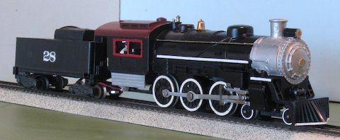
The Ten Wheeler is a sharp reminder of the long past glory days of steam railroading.
End of part 4 – Stumpy Stone
__________________________
May 2, 2014
Stumpy’s Station – “Out of the Woods” Part One
One of the more neglected layout themes in S gauge is logging. Few have done extensive logging sections on their layout, or at least a portion of a large layout. This is partly because it is not a widely known theme in S, and partly because everyone equates logging with geared locomotives such as the Shay, Climax, or Heisler engines. These were available only in brass some time ago and quite expensive.
The geared locomotives were very popular in the timber industry during the steam era due to their high power to size ratio, ability to take sharp curves, and operate on poor track. They could be found from the Sierras to the mountains of West Virginia trundling long trains of Skeleton log cars or flatcars converted for timbering uses.
The vision is well known and accepted by most people as the way logging was. Without a Shay and a string of brass log cars, most folks feel that they can’t do logging on a portion of their layout, let alone develop a whole layout around such a theme. But that is just plain wrong!
There were several logging operations that used side rod locomotives to get timber out of the woods. Probably the best known of these was the Rayonier Company which used large (for short lines) 2-6-6-2 articulated locomotives and low drivered 2-8-2 Mikados. There were several other “side rod loggers,” and these used steam well into the diesel age. In fact, these side rod logging engines survived to go on to second (or third or fourth) careers on tourist railroads and in motion pictures, including lots of screen time in “Emperor of the North.”
Where distance and terrain made geared engines much too slow, side rod steam locomotives ruled! And they weren’t always big engines. Locomotives as small as the 8 ton Porter 0-4-0 tank loco found use in smaller operations. And the Porter Locomotive Company built a huge number of side rod type locos for the logging industry, many tank engines and heavy 2-6-2 and 2-8-2 tender types with very small diameter driving wheels for power and traction. Many lower budget loggers snatched up whatever used motive power they could buy from mainline railroads.
The second problem most folks run up against to portray logging is the lack of log cars, particularly the Skeleton Log cars, so named because they are a center beam with cross arms at 90 degrees to the center line. They take their name from their look of a human back bone and ribs.
Skeleton Cars were built in length as little as 22 feet long to 36 and 40 feet. The numerous Car Builders not only made complete cars, but supplied trucks, couplers, and various other parts to logging outfits who built their own cars. Generally the earlier cars were wood, and timber companies saw little reason to change when they could build as many cars as they needed from wood they already were cutting!
Another way to get log cars was for these companies to buy used mainline flatcars and convert them for their own use. There were hundreds of well worn 36 foot wood cars on logging roads all over America. In later years companies bought the sturdier steel frame 40’ flat cars.
Flat cars were often modified with Log Bunks near both ends and evenly spaced in the middle. In this way, odd shaped logs could ride without having to be loaded flat to the car’s deck. These could be removed to use the car for other purposes such as hauling various supplies, or equipment like a “Donkey Engine” (a steam powered winch on skids) so named because they replaced animals for dragging logs to the railhead.
Usually, cabooses were not used on log trains due to the lack of switching and little real need for them. However, some operators built shacks on flat cars and there were others built on a four wheel frame called “Outhouse” cabooses because of their similar appearance to that well known “facility” of the day.
In this series, we’re going to build log cars and an Outhouse caboose to depict the timber industry in S gauge. For motive power, you could use a 2-6-2 Prairie similar to the one we recently built in STUMPY’S STATION, or a Gilbert 0-8-0, a Flyonel 2-8-2 or Docksider, the SHS 2-8-0, or any of the older “hood unit” diesel switchers, to bring the timber out of the woods and to the sawmill.
You don’t even need a huge sawmill or a thousand trees. I built a 34×48 inch S gauge Mini layout with 15” radius curves several years ago that depicted a logging line in between the actual tree felling area in the woods and the sawmill. I used only a few smaller “new growth” sized trees and several tree stumps because the line would naturally pass through areas where the timber had all been cut! The few structures were small wooden ones. A Putt Trains 0-4-0 Dockside, and 2-4-4 Suburban worked the line pulling scratch built Skeleton cars.
In this series we won’t “break the bank” to bring timber “out of the woods!”
End of Part 1 – Stumpy Stone
___________________________
April 4, 2014
Stumpy’s Station – “Out of the Woods” Part Two
We’ll get started by building those unique wood based Skeleton Log Cars. Two lengths will be built, the 22 foot “shorty” cars and the more common 36 foot cars. All will be of the basic style using lots of wood with trucks and hardware made or iron or steel. Not only did the Car Building companies build them this way, but they supplied trucks, couplers, and assembly hardware to timber outfits to build their own cars as well.
An interesting note here is that many log cars had no brakes. When parked, the wheels had to be chocked to keep them from rolling. Those with brakes often had the brake staff and wheel removable to clear logs, or had these parts moved to the side of the car for clearance. For logging operations in the days of steam machinery, safety was often given only a passing thought! Even today, it remains a dangerous occupation.
The basic design will be the same for both 22’ and 36’ cars, only center beam dimensions will differ. The long “bunks” which actually hold the logs in place across the car will be of the same dimensions for both cars, as will the “bolsters” where trucks are mounted to the car.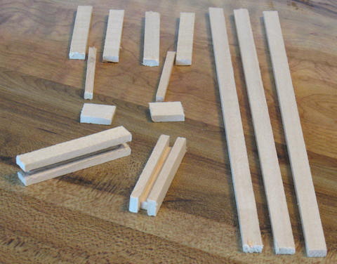
You’ll need two pieces of 1/8×1/4 inch strip wood or balsa 1 ¾ inches long and a piece of 1/8×1/8” wood 1 ½” long for EACH bunk. The 1/8×1/8” will be glued between the two 1/8×1/4” pieces to form a “U” shape if seen from the end. All three pieces are 1/8” wide, but the center must be lower than the two outside ones and 1/8” shorter at each end.
The 22 foot Skeleton Car will need two bunks, and the 36 foot car will need four bunks.
The center beams for the Skeleton Log Cars will be made of three pieces of 1/8×1/4” strip wood or balsa glued together side by side standing on edge. For the 22’ car, cut these 4 3/16” long. For the 36’ car cut them 7” long. This will make a heavy center beam that will act as the car’s “frame.” You might score the edges of each board the enhance the appearance of being separate timbers.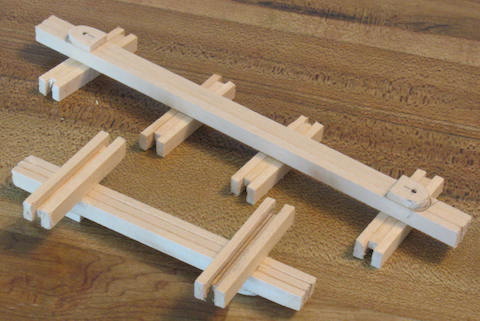
Once the center beam glue is dry, you can add the “bolsters” which are made of two pieces of 1/8x 3/8” strip wood cut ½” long for each bolster. (Do NOT drill holes for the mounting screw yet!) The bolsters will be glued to what will be the “bottom” of the center beam. The beam is 3/8” wide, so the half inch length of the bolster will be along the beam, not across it.
In the case of trucks with couplers mounted on them (such as SHS) you’ll want to round off the end of the bolster facing the end of the car for clearance
of swing. From the end of the beam to the bolster’s rounded end will be 9/16”. Do this measuring from both ends. Only after the glue attaching bolsters to the beam has completely set will you drill a 1/16” pilot hole through the bolster and into the center beam. The hole will be in the center of the bolster (¼” from the ends and 1/8” from the sides.) The reason for drilling after gluing is to limit possible splitting of the wood of the bolster.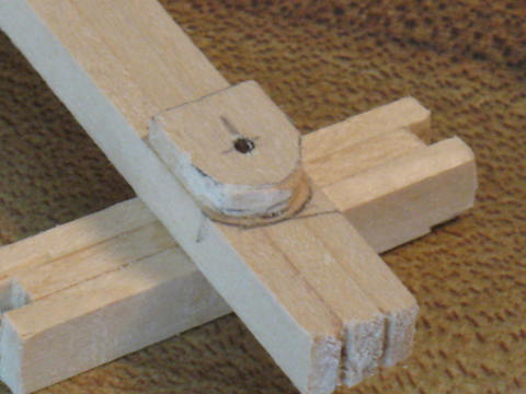
Once the bolsters are secure, turn the center beam over to mount the log bunks. In the case of both lengths of cars, glue the bunks 11/16” from the beam ends. This will put them over the drilled holes. The bunks should be glued on with the middle 1/8×1/8” piece against the center beam. This leaves the “open center” side up.
In the case of the longer car, you’ll be mounting two more bunks to the center beam. Each of these will be mounted 1 ½” from the end bunks. You may wish to move these two “middle” bunks to make either the look of equal spacing or make them be a bit closer to the end bunks. Some loggers added a fifth bunk, while others used only three bunks instead of four, so there is some latitude in being realistic.
Okay, the basic car is now ready for trucks and couplers, and this simple design allows for either Hi-Rail or scale mounting. Scale modelers may want to use a spacer between the bottom of the center beam and the coupler box to get correct height. The threaded portion of the truck screw can usually be up to 1/8” in diameter without causing splitting problems. Smaller screws are better. Use a small washer between the bolster and the truck. If your screws are too long, uses washers between the screw head and the under side of the truck but beware of rail clearance.
Now take the screws, trucks, (and Hi-Rail couplers) off. You’re going to do some work in the model Blacksmith Shop now to make the various hardware that is supposed to hold the car together. Fortunately, you don’t have to fire up a forge to heat iron because we’re going to use card stock! More about these details next time.
For cars like these, you may find it a good plan to build a few at the same time, almost like an assembly line way.
End of part 2 – Stumpy Stone
_______________________________
May 6, 2014
Stumpy’s Station – “Out of the Woods” Part Three
Your log car is built and now it’s time for details and painting. Last time we were going to “forge” iron parts. But we’ll use card stock. The first parts are straps or “bands” to hold the center beam together. They are made of 1/8” wide strips 15/16” long. Into the first ¼” of each end, use a ballpoint pen to press a pair of “bolt heads” into the bands. Two bolts of each side of the car. Once pressed, carefully bend the card stock around the center beam (there will be no strap across the car bottom.) When you glue each band on, it should appear as if the bolts go through the beams to the far side, thereby holding the beams together. And remember the pressed “bolt heads” face out!
Bands will go around the beam at each end, beside each log bunk on both sides, and the last few equally spaced along the beam between the bunks. Again, with so many variations in the real cars, it’s hard to get the spacing “incorrect.”
Some Skeleton log cars had additional strap iron from the center beam to the top of the middle part of each log bunk. This not only strengthen the bunks connection to the center beam, but allowed logs to slide up these onto the bunk without catching on the sides of it. This is an option you might consider which will be just four more 1/8” wide strips of card stock per log bunk.
Next, you’ll need to make iron straps for the ends of the log bunks to hold stakes. These will be made the same way, to the same length as the center beam bands. You’ll need two straps for each bunk, one at each end. Make sure there is a 1/8×1/8” opening to insert a stake (which you’ll do later.)
Some loggers trimmed down and “jammed” stakes into place, while others preferred to run a long bolt through the log bunk end to “pin” the stakes in place. This can be represented by a tiny drop of glue to form a “bolt head” on each side of the bunk ends. Others used triangular wedges that could slide in the open center of the log bunks to adjust position for the logs. You can make wedges of 1/8×1/4” strip wood cut diagonally. In the case of using wedges, strong chains held the logs both together and securely to the car.
For a brand new car from one of the major Car Builders, the wood and iron parts were universally painted to the customer’s color specifications, usually gray or black, but other colors were used. In later years “Safety” yellow or orange became popular. For a car fresh out of the logger’s shop, the wood can be left unpainted, but the iron bands and straps will need to be painted black.
As cars aged, the paint became faded and chipped and the metal hardware got rusty. Creating the “aged” wood look is difficult, so I paint the wood a light gray, often using a light “wash” of darker gray or even a little black.
Hardware gets a wash or coat of “Rust” color or a dull light brown over the iron black paint. Sometimes one band could be left black to show that it has been replaced or just hasn’t started to rust as fast as the others.
By the way, “rust” is not always the same color! Different alloys of metals oxidize to different shades of red, orange, or brown, and the age of the rust seems to darken the color of the rust, especially on heavy cast iron. If you want to start an argument among model railroaders get a group of them together to tell you what color “rust” is!
You may want to weather and/or “rust” the trucks and couplers for log cars as well. Equipment used in the timber industry was rarely well maintained, at least cosmetically, with the occasional exception of the locomotives or other steam machinery.
Skeleton Log cars were seldom lettered for the company they were owned by because they didn’t leave company rails! Not all cars were numbered either and those which were had their numbers “touched up” or replaced by hand painted numbers, usually not too neatly. This “hand painting” can be done by carefully using a toothpick dipped in paint to hand apply numbers.
When logs or cut lumber were shipped off line, they generally used regular railroad flat cars, but for our purposes, Skeleton cars can be used anywhere.
After you have detailed, painted, and assembled the Skeleton car, the last thing to do is put long stakes in each end of the log bunks. I use 1/8×1/8” strip wood ¾” long for stakes. ½” of each stake is above the log bunk to hold the lower logs from rolling off the car. These are left natural bare wood color because they were broken often and replaced quickly and cheaply. I sand or carve with a hobby knife some rounded edges on the portion of the stake extending above the log bunk to depict the wear of constant loading and unloading.
Skeleton cars were also made in all steel, but by this time many logging operations were moving to trucks and heavy equipment. Rail based operations were in decline and usually opted to buy used rolling stock and locomotives to hang on until they could change operations to the road.
More “Out of the Woods” next time.
End of Part 3 – Stumpy Stone
_____________________________
June 4, 2014
Stumpy’s Station – “Out of the Woods” Part Four
While Skeleton log cars were unique to the timber industry, many logging railroads used common flat cars for hauling the logs or equipment needed into the woods. The flat car was more versatile and could be had used from mainline railroads very reasonably.
Most of these cars were used with long stakes in the standard stake pockets to keep the timber aboard. A few had log bunks mounted on them.
While many loggers used steam “donkey engines” with winches and cables at a forest “load out” location. Other companies mounted light rail on the flat cars and used moving cranes running on these rails to load the cars. These could run the length of the empty cars and load the train one car at a time until they worked their way to the end. Other loggers stationed rail cranes at locations until the area was “logged out” and then moved them to the next site.
The flat car is a common car and instead of build one here, you can simply buy a well used American Flyer car inexpensively and put scribed balsa decking on it. Add some weathering and you’re set. If you want to build a car from scratch, allow me to direct you to my “Easy S Scratch Building Rolling Stock Guide” to be found elsewhere here on My Flyer Trains.
One of the cars that was especially unique and characteristic to industrial railroads was the “Outhouse” caboose. Basically this was a shack on a single four wheel truck in many cases, although some larger, purpose built four wheel cars were made which were known on regular railroads as a “Bobber” caboose.
The outhouse car was a tiny office for the foreman at the “load out,” carried train crew, or transported tools. Usually only larger operations had enough railroad to use a conductor on a train, but a place for brakemen to ride was needed if the locomotive cab was too crowded.
The tiny four wheeled car looked somewhat like the infamous “restroom” of the day, hence the nickname “Outhouse” for these cars (although I can’t find reference to them having a “facility” inside.) Today we might call them “Porta Potty” cabooses!
Our “Outhouse Caboose” starts with a single truck of any brand that you wish. Since the caboose was the last car in a train, only a single coupler is required. Since trucks and couplers usually come in pairs, you might make two of these tiny cars or save the extra for another project.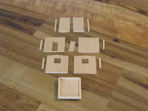
The “floor” will be a piece of scribed balsa sheet with 1/8” “boards.” We’ll use this same material for the sides and roof as well. The floor will be 1 ¾” long by 1 5/8” wide. Run the boards end to end for the car and they’ll be on the bottom.
Next, you can make a “bolster” from 2 pieces of 1/8×1/2” strip wood, each ½” long. Glue these one on top of the other. While the glue is setting on these, drill a 1/16” pilot hole in the center of the floor.
Once the glue of the bolster pieces are set, glue them to the center of the bottom of the car. Since the bolster on this car does not have to allow for swing, the bolster will mount the truck and coupler solidly with a small screw. With the glue set between bolster and floor, drill a 1/16” pilot hole through the bolster, using the hole in the floor as a guide.
Wall braces must be made for the upper side of the floor. These will be made of 1/8×1/8” strip wood, 2 are 1 ¾” long, and 2 will be 1 3/8” long. The longer ones go atop the edges of the floor the length of the car, and the shorter ones between them at the end edges.
Now we’ll do some careful cutting on the 1/8” scribed sheet balsa to make walls with a door and windows. Balsa cuts easily with a sharp hobby knife, so all you have to do is mark the area carefully and cut slowly with several even strokes of the knife.
The side walls of the Outhouse caboose will be the same sheet balsa used for the floor and the boards will run vertical. These walls will be 1 ¾” high by 1 ¾” wide. On one side wall, carefully cut out the door opening which will be 1 1/8” vertically by 7/16” wide and the bottom of the door opening will be 1/8” up from the bottom of the side wall. Save the piece removed as it will be the door. Use a slice of small dowel or a sliver of balsa for a “door handle.”
The end walls will start as a piece of balsa sheet cut 1 7/8” high (remember the boards go vertical) and 1 ¾” wide. This extra width will allow for the end walls to overlap the side walls.
Once you have these pieces cut out, mark the center of what will be the top of each end wall. Then measure 1/8” down each side of the end walls and mark that. Draw a line from the side marks to the center mark to show what needs to be cut away to create the shallow roof pitch on both end walls.
Now mark and cut the windows. The windows will be 1/2×1/2” square. Each will be centered on the wall with the bottom of the window 1” from the bottom of the wall.
End of Part 4 – Stumpy Stone
____________________________
Stumpy’s Station – “Our of the Woods” Part Five
Last time, we cut out the balsa sheet walls for our Outhouse Caboose. Our next task is to make door and window “frames” from 1/8” wide strips of card stocks and glue these to the walls. Make the vertical “frame boards” The length of the sides of the door or window openings and glue them on. The horizontal “frame boards” should be longer in order to overlap the side boards and create a square border around the windows and door.
While the frames are drying, cut four strips of 1/8×1/8” strip wood 1” long. These will be glued to the vertical edges of the side walls on the “inside” to brace the walls as they are glued together. You’ll recall that we already added this sort of bracing to the floor.
Glue one wall at a time to the floor, blocking the floor and wall into a square right angle until the glue sets. The bottom of each wall will be even with the bottom of the floor. I started on the door wall and worked my way around the car. With the walls and floor assembled, it’s time to make two roof haves. Each of these will be 2” long by 1” wide. The scribed boards run long ways.
Before you mount the roof, paint the interior of the car black. Once the paint dries, cut out two 3/4×3/4” pieces of clear plastic for window “glass.” Glue these to the inside of the car. I use the “free” plastic cut from “blister packs” that many products come on cardboard display cards.
Next, we’ll have to install the door. Here’s where I discovered a trick a long time ago that you might want to try. Glue a piece of card stock to the back (unscribed side) of the door 1 ¼” high by 5/8” wide. Glue this so that the card stock does not go beyond the bottom of the door and interfere with the floor to wall bracing. Paint the card stock black around the edges of the door.
Next paint the walls and the door itself the color of the finished car. Work carefully around the edges of the door itself. When you glue the door/card stock to the inside of the wall, you’ll notice that the edges of the door will stand out visually, giving an enhanced impression of a working door.
Once the door is in, we’ll go back to the roof. Cut two pieces of 1/8×1/8” strip wood to brace the roof halves. Glue these to the unscribed side of each roof half along the edge that will be the center of the roof. Once the glue is set, place these in position and notice that you’ll have to file away a bit of the these braced to get the two roof halves to fit together at the roof’s peak.
We’ll mount the roof and other items next time.
End of Part 5 – Stumpy Stone
_____________________________
August 8, 2014
Stumpy’s Station – “Out of the Woods” Part Six
The windows are in, the door installed and the roof is ready to go on if you’ve filed the braces to shape. Go ahead and glue it on, allowing a bit of overhang on each end and the sides.
Obviously, the roof had to be covered to keep it from leaking. This was often done by applying tarred canvas, and later with regular roll roofing material. The roof was covered in the same manner as any other building. To depict either of these in texture, common ¾” mashing tape will stand in.
Start at the bottom edges of the roof and overlap the next layer slightly as you move to the top of the roof. Wrap the ends of the tape over the edges of the roof at each end of the car and trim off the excess. Also trim off any excess tape when you reach the roof peak. Cut a 3/8” inch wide strip and apply it to equal width along the center of the roof peak to overlap the tape on both sides of the roof. This keeps rain from getting under the roll roofing at the peak.
If you wish to give your Outhouse Caboose a “worn” look, you might wrinkle the tape as you apply it or tear pieces of it as if the roofing was coming loose with age. When done, paint the roofing black. Under the roof, paint the underside of the roof overhang the car’s color.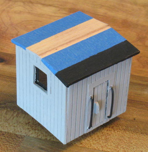
Many of these tiny cars has a small wood stove inside for winter heating, so we need to add a stack of some kind. This can be as simple as drilling a hole in the roof and using a piece of brass or plastic tubing. To keep rain out, use a paper punch to pop out a disc of card stock and add it to the top of the stack.
An alternative is to use a small diameter flexible alcoholic beverage stir straw to have the stove pipe come out an end wall, turn 90 degrees and go up the side of the car. A regular “flexi-straw” is really too big in diameter, but could be used. Stove pipes would be black, maybe with a little rust.
How does anyone get into the car? Well, next we’ll put handrails on either side of the door. I like to use “mechanic’s” or “farmer’s” tie wire. This is a very flexible mild steel wire less than 1/16” thick. Cut two pieces of tie wire 1 3/8” long and make a 90 degree bend in each end with about ¼” “legs.” These legs will go into holes drilled in the side of the car either side of the door frame. To attach them, put a drop of glue in each hole and carefully place each end of the handrail in the hole, leaving a gap of about 1/8” between the railing and the car side.
Often, anyone entering the door would grab a handrail and use the truck as a step to get into the car. However, some companies used a ladder of some kind, usually made somewhat like a strap step, while others preferred wooden steps on iron hangers.
To make the wooden with iron hanger style steps, all you need do is cut seven pieces of 1/16×1/8” strip wood ½” long, or cut these parts out of left over scribed balsa sheet. Two of these will represent vertical “iron hangers,” one will be the horizontal brace across the “back” of these “hangers” at their upper ends. The other three will be the evenly spaced “steps,” one at the bottom, one halfway up the hangers, and one just below the top of the hangers.
Once the gluing is done. Glue the “brace” end to the car floor directly below the door and handrails. The “hangers” could be painted black, the rest the car’s color, or the entire part could be the same.
An addition to this car could be a small red flag sticking out of the opposite end of the car from the coupler. A length of “cable” might be hanging on the side or rear of the car. This might be just string painted gray, black, or “rust” color. The paint drying stiffens the string and makes it easy to glue to the car body. A detail casting of a lantern and a few “waybills” or “notices” tacked to the car side would make a nice addition as well.
Since Outhouse Cabooses tended to “get no respect” you might try your skills at “weathering” the paint job, very suitable if you have made the “roll roofing” look damaged.
The construction methods you have learned will also allow you to try building wooden “house cars” (box cars, reefers, etc.) and if you leave off the truck, coupler, hand railings and steps off, you have a nice model of a small trackside shack.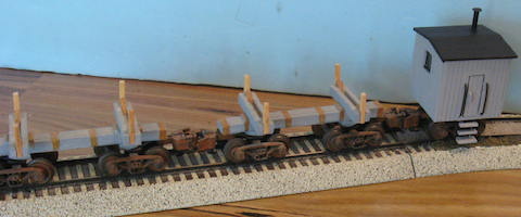
This completes the series on logging. These cars seldom saw mainline use, but the theme of a small logging line would be excellent for layout builders with limited space. As I said at the beginning, this would be a good use for the AF 0-8-0 switcher or 4-4-0 Casey Jones, the SHS 2-8-0, the Flyonel 0-6-0 “Docksider” tank loco, or in more modern eras, diesel switchers or road switchers like the “Geeps.”
For scenery, just buy up a bunch of model trees, some small footprint buildings, and a few ragged old trucks. You might even find researching logging railroads and operations a lot of fun too.
End of Part 6 – Stumpy Stone
_____________________________
September 1, 2013
Stumpy’s Station – “Prairie Dog” Part One
With this, we begin another multiple part locomotive kit bashing project of a comparatively common American Flyer steam engine, the plastic boiler shelled (#282 etc.) Pacific. You can find these in junk boxes almost as easily as the plastic boiler Atlantic. Even one purchased complete and running off a vendor’s table can be had for between $50. and $70. Any higher price than that takes it beyond “bash quality.”
If your engine doesn’t come with the later, common plastic tender, get one of those too, or a Franklin tender, or a Marx tender.
In this series I will turn the common plastic Pacific, which pretty much represents a “modern” engine built in the twenties and thirties, to a Turn of the Century locomotive not commonly seen. This was the 2-6-2 Prairie.
Let’s start with some history: By 1890, the railroad car builders had begun using a lot of steel because this stronger metal was able to support longer cars and heavier loads than the wood which had been used until then. This led to the cars themselves also being heavier. Increased traffic required longer trains.
The engines mostly in use at this time were the 4-4-0 American, 2-6-0 Mogul, and 2-8-0 Consolidation wheel arrangements with the fireboxes between the driving wheels. (Unlike most people’s guess, the 2-8-0 Consolidation, not the 4-4-0 was the most produced locomotive in history.) To pull the increased weight and length of trains, boiler and firebox size had to be expanded. For this reason, locomotive builders and the railroads themselves began considering the placement of a larger firebox behind the rear drivers and as wide as the clearances allowed. To carry the addition weight, a “trailing truck” would have to be used.
On the earliest of these experiments this “trailing truck” did not move laterally and increased the wheelbase of the locomotive. By making the rear truck “swing” the locomotive could operate more reliably through tighter curves such as those found in rail yards or on branch lines.
With the firebox moved back, the boiler size could also be lengthened. This provided longer flue length, hence more water evaporated into steam, and the added weight created more traction. In the first experiments the 4-4-0 American became a 4-4-2 Atlantic, and the 2-6-0 Mogul became a 2-6-2 Prairie.
The 2-6-2 Prairie was built as both passenger and freight type engines, the size of the drivers being the deciding factor. The Prairie was also the first engine to be seen by many roads as a “Dual Purpose” locomotive when equipped with “medium size” drivers, being used for passenger locals and fast freight service interchangeably. As they were demoted to low grade service in later years this trend continued, and on some small roads was expanded. The 2-6-2 also became the “big power” on many logging, mining, and industrial railways.
Unfortunately, in this era of “cut and try” technology, many of these early 4-4-2 Atlantic and 2-6-2 Prairie engines had stability and balance problems. The railroads themselves made running changes, and this led to a second generation of wide firebox/trailing truck locomotives.
By proving the concept, the Atlantics and Prairies were soon relegated to secondary service or sold off to smaller railroads to make room on the roster for the 4-6-2 Pacific and 2-8-2 Mikado. The last Class One railroad to use 2-6-2’s was the Nickel Plate Road, which used them as branch line power into 1957. For this reason, the lowly Prairie can be placed on your railroad right up to the end of the Steam Era.
Our “Prairie Dog” project will depict a Prairie which might have been built in about 1910, and updated over the years to run until the end of steam, probably on a Class Two or “Shortline” railroad.
There will be changes to the lead and trailing trucks on the locomotive chassis, and the tender. Most of the customizing will take place on the plastic boiler shell to backdate it to that early 20th Century look. I’ll use weathering to age the older style engine to look as it might when it was last operated in about 1957.
To speed up the whole process, I’ll forgo the information on purchasing, cleaning, inspecting, and repairing the locomotive. This can be found in the “Project Atlantic” series here on the My Flyer Trains website, Stumpy’s Station section. More information can be found in depth in the “Guide to Kit bashing American Flyer Steam Locomotives,” also here on My Flyer Trains.
End of Part 1 – Stumpy Stone
______________________________
October 3, 2013
Stumpy’s Station – “Prairie Dog” Part Two
We’ll start off by removing the boiler shell from the locomotive chassis and tender shell from the tender chassis. To build our “end of steam” version of the 2-6-2 Prairie, you’ll want to get a later American Flyer Pacific 2 wheel trailing truck with the outside bearing frame, or order one of these from LBR Enterprises at: lbrenterprisesllc.com
Of course, the first thing we have to do to change the AF Pacific into a Prairie is to remove one axle from the four wheel “pilot” or lead truck of the Pacific. Remove the front truck/valve crosshead assembly from the engine. This assembly generally has the truck riveted to the crosshead with a coil spring between crosshead and truck frame.
Turn this assembly over until the underside of the truck frame is “up.” Cut the truck frame about half an inch from the center spring/rivet so that you have just a two wheel lead truck assembly. While you can hand saw, I have found a Dremel tool to be far better for this. The rapid cutting motor tool will heat up this part quickly, so work in spurts or wear gloves!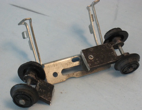
The frame and wheels still attached to the crosshead is now the two wheel Prairie “lead truck” and the cut off piece goes to the scrap/parts bin.
If you had a cast lead truck frame for this, you’ll probably not need any additional weight between the coil spring and front axle. If you have the stamped steel pilot truck frame, a bit of lead weight will be required. In either case, the strength of the spring will often determine if you need weight and how much. I like to use the lead sheet available at hobby shops as it can easily be bent and cut. Tungsten is a new material that is popular in Pinewood Derby racing because of it’s heavier weight for the size, but is VERY hard to cut and work.
Now, lets go to the rear of the locomotive chassis. Since the old 1910 locomotive would probably been upgraded from it’s inside bearing trailing truck at some point, you’ll want to get an outside bearing trailing truck. You have three options; 1. Find an original American Flyer later Pacific two wheel trailing truck. 2. Get the two wheel trailing truck from LBR Enterprises. 3. Get a two wheel truck COVER from LBR to use on the original tender drawbar if you use the 4-6-2 tender. If you change tenders as I did, you’ll need option 1 or 2.
If you use the LBR two wheel truck cover, you simply attach the part over the original trailing truck. If you use the complete trailing truck option, you’ll have to remove the original truck wheels and axle by grinding off the rivet. Once this is done, the complete truck will fit right in the hump in the drawbar left open with removal of original wheels and axle.
Another option would be to remove the entire original drawbar by grinding off the rivet on the tender and making a new drawbar from wood, metal, or heavy wire. This would allow you to get the tender prototypically closer the locomotive cab too.
I have successfully used Popsicle (craft) sticks cut to length and holes drilled for a bolt and nut to attach to the tender. At the other end, an old Flyer or LBR two wheel trailing truck can then be placed in position, and if the truck casting at the pivot point is filed down, the original mounting screw can be used.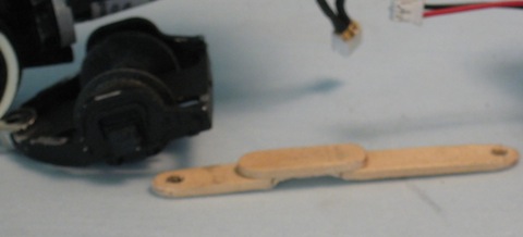
In the case of this project, I had the make a slightly different wood drawbar by doubling the Popsicle sticks at a point where the drawbar went over the trailing truck. I then filed the portion of the “lower” stick away over the trailing truck. The drawbar now had a “hump” in it for clearance.
This will also work with changing to a Franklin style or other tender because you have to make a new drawbar anyway and allow the engine trailing truck to pivot separately. Changing tenders makes an instant visual change to the appearance of any locomotive, particularly the more common Flyer ones everyone is so used to seeing.
On my locomotive, I decided to use an old Marx 3/16 size tender. This required that I come up with a new floor for the tender shell to mount S gauge trucks and couplers.
There are two options for this. 1. An AF tender floor cut down, or 2. Make your own new tender floor.
An old Flyer tender floor was too long, so I cut equal lengths from both ends until the floor fit under the Marx tender. Holes for mounting screws were the only other modifications.
On an earlier project where the tender floor was badly rusted, I made my own floor out of sheet balsa and strip wood and used American Models trucks and with their electrical pick ups. I only needed a coupler on the rear truck of course.
End of Part 2 – Stumpy Stone
_____________________________
November 4, 2013
Stumpy’s Station – “Prairie Dog” Part Three
If you have built last year’s “Project Atlantic” you will find much of the following to be old news. We’re going to move some details around to give the locomotive a different look.
We’ll start by removing the cast metal bell from the plastic shell. These are pressed in, not glued, so you can pull them out. Work carefully so as not to damage them. A little firm prying with a screwdriver is better than the crushing grip of vice grips!
Next, we’ll remove the bell mounting bracket by carefully cutting it of with a hobby saw. File and sand the remaining area smooth to make it look like there was never a bracket there. This will destroy the bolt detail, so you’ll have to “make” replacement bolts. This step will be better done after the headlight is removed.
Next, remove the headlight lens (you can often just place a small screwdriver behind it inside the shell and pop it out) and cut the headlight and bracket off. Fill the headlight hole with a piece of plastic rod, wooden dowel, or putty, and sand smooth. For all such “body work,” use gray primer to bring out the surface to check your work. Sand/paint/sand/paint as necessary until smooth just as auto body shops do to make car body surfaces smooth.
Stand the shell up so that the boiler front is flat and use a toothpick to place small dots of white glue in place of the missing bolt heads. This takes a steady hand and patience. Start small, allow to dry completely, and build up the glue dots until they are about the same size as the original ones. Use gray primer to check the placement and size each time and also to seal the white glue.
With the shell standing on end, you may also want to place a “number plate” in the center of the boiler front. You can buy these as detail parts or make your own quite easily and cheaply. I use a common paper punch and punch-out three to five circles of cardstock (3×5” file card, available at office supply or craft stores very inexpensively.) I glue these together in a “stack” and then glue this “number plate disc” to the center of the boiler front. Paint with gray primer to “seal” the part.
Next, drill a 1/16 inch hole atop the boiler between the domes for the bell, but don’t glue it in until all painting is done.
By the way, Duco Cement from the home supply store, or Walther’s Goo from the hobby shop work well for adding such details.
To back date the engine somewhat, we’re going to mount a headlight on top of the boiler. Up until the Turn of the Century, placement of the headlight high up was in vogue because they were kerosene fueled. The need to get as much light as possible on the tracks ahead pretty much required such a high mounting.
However, with the use of electric lights, powered by a steam generator, some railroads began mounting the headlight on the upper smokebox front or in the center of the boiler. Therefore, a headlight mounted high atop the boiler gives the engine’s profile an older appearance.
Quite possibly an early 2-6-2 would have a square headlight atop the boiler. However, since we’re representing our “Prairie Dog” as it would be later on, after years of upgrades, we’ll use a cylindrical headlight.
So that we can use light from the regular headlight bulb, drill a 1/16” pilot hole in the exact center of the top of the boiler shell about a quarter inch behind the boiler front. To get this right, it is easier to measure and work from the inside of the boiler shell. In this way, you don’t drill into the thickness of the plastic of the boiler front and block some of the light off.
The actual finished light accessing hole would then be drilled to a “loose” 1/8,” and no more than 3/16” inch.
We’ll make our more modern headlight from a piece of 5/16” outside diameter plastic tubing, about the same diameter as the cut off headlight and big enough to put the original lens in. This plastic tubing should be 1/2“ long.
Drill a hole in what will be the “bottom” of the headlight tubing so that with the headlight protruding slightly in front of the boiler front, the hole lines up with the hole in the top of the boiler shell. This will allow the light to enter the headlight and be channeled through the plastic lens like a crude form of fiber optics. The inside of the headlight tubing should be white to further help the light on it’s way by reflection.
Cut a piece of flat material (plastic, wood, even cardstock) to the back of the headlight, or putty the back of the headlight tube closed. File the “bottom” of the headlight tube slightly flat and glue it into position on the top of the boiler.
When the glue is set, paint the headlight and entire smokebox with gray primer. You will insert the lens later after all painting is done.
End of Part 3 – Stumpy Stone
______________________________
December 3, 2013
Stumpy’s Station – “Prairie Dog” Part Four
Older locos had taller stacks because boiler diameters were generally smaller and there was the need to raise the smoke above the cab. Later locomotives had larger diameter boilers to increase power, so to fit the clearances of tunnels and low bridges, the stack got shorter.
To raise the stack, we’ll use a piece of plastic tubing to match the outside diameter of the original smoke stack, just a tad smaller than 1/2inch. (You can always file the diameter the small amount to match the original stack diameter.) We’re adding just 1/8” to the stack, so you’ll be carefully cutting a “ring” from the plastic tubing. Glue this to the top of the stack.
Another thing that was a hallmark of many old locos is a pronounced flange around the top of the stack, called a “capped stack.” This can be made in two ways; 1. Use very thin model auto pinstripe tape wrapped around the stack until a ring is easily visible (about three rounds.) 2. Get a small rubber O-ring from the home supply or auto parts store with a slightly smaller diameter than ½” and stretch this over the top edge of the stack. Mine came from the NAPA Auto Parts and is 3/8” Inside diameter and 1/16” thick. I dabbed glue on the stack extension and stretched the o-ring on. Once the glue is set, paint with a couple coats of gray primer to “seal” the work.
There is an alternative to making these “back dating” parts. Find a Casey Jones loco shell and cut off the headlight, stack, number plate, even the bell and cowcatcher for parts to graft onto the “Prairie Dog.”
The Casey Jones, like the F-9 diesel, are examples of a failing American Flyer going “on the cheap” to survive. Both are poor running and poor looking locomotives (particularly the F-9), a sad farce of the quality and semi-scale fidelity American Flyer had been known for.
The common Casey Jones can be had from parts boxes under tables at train shows, or whole, running locos and tenders can be bought for $10. to $25. Paying more is robbery. The exception is the better #21168 Southern version which had smoke and reasonably correct side and main rods. These often demand $70. to $120. depending on condition. Cutting one of the Southern Casey Jones up for parts will have lynching parties of collectors at your door.
It seems a shame to “waste” a locomotive, no matter how poor, but there is always something else you can make out of “parts.” For instance, you have a plastic tender for customizing or up dating a Franklin project.
The boiler without stack, headlight, bell, cowcatcher, boiler front, domes, and cab can be reworked with a few internal pieces made from card stock and a good coating of “rust” colored paint to be a “scrap boiler” beside an engine house, or as a flat car load.
Even the chassis can be stripped of the drivers so they can be used parts or scrap too. Keep that pilot truck for other uses too, like a track “Speeder” chassis topped by a card stock or plastic body. Again it’s scenery detail you might pay good money for that you can build yourself far cheaper.
One of the things I like to do on all my locomotives is to put an engineer at the throttle. This icon of the steam age, arm on the window, watching the track ahead, brings “life” to your locomotives.
On the Flyer Pacific, it will be necessary to remove the bar in the center of the cab window to get a figure in there. I like to use figures by “Fun n’ Games” miniatures. Their website is: http://scalefigures.com/ . I like their S scale numbers S223 or SA005 Engineers. It may be necessary to bend or cut off a leg to get them in and still clear the motor, depending on if you’re using the Flyer motor or a DC can motor.
I have used a number of the Fun n’ Games figures in three scales and they are nice. The standing figures have a pin cast into one foot so that you can mount them anywhere on the layout and they remain standing. If you don’t want to use the pin, it pulls right out with a firm tug with needle nose pliers.
You can also place a fireman on the other side of the cab by the same process. On stoker fed boilers, the fireman spent more time on his seat watching gauges, for signals on his side of the boiler, and attended to feeding the fuel and water to the boiler by use of hand controls.
On non-stoker equipped locomotives, he would spend a lot of his time hand shoveling coal into the firebox. Depending on how much steam the engineer, load, and schedule demanded, he would get little “seat time!”
End of Part 4 -Stumpy Stone
______________________________
December 31, 2013
Stumpy’s Station – “Prairie Dog” Part Five
Well, our project is into the later stages now. It’s time to paint the loco and tender shells. Obviously, the basic color will be black as was traditional from the late 1880’s onward, except for special passenger train and streamlined locomotives. This trend was started by Vanderbilt on the New York Central to cut cleaning costs required by the earlier, fancier locomotives.
The cab roof and tender deck (behind the coal bunker) was painted Pennsylvania Tuscan red. Actually, The Pennsy did this for rust prevention when putting locomotives into storage. They just left the Tuscan alone when the loco went back into service. Other roads started using it as an appearance thing.
The smokebox was painted gray to give a dull graphite look. Paint burned off areas where the boiler was not covered with insulation and jacketing; the smokebox and firebox. Therefore spreading graphite on these areas protected them. Depending upon how the graphite was mixed, applied, and how long the engine had been in the weather, the graphite could range from a nice silver to gray to a dirty white color, this last being either engines long stored or neglected. Many roads also mixed carbon black with graphite to make the boiler a uniform black color.
The running board edges and lead truck rims were painted white to match the “wide white wall” driver tires. White driver tires were a maintenance habit to help crews spot cracks in the tires.
To “back date” the loco, the railings along the sides of the boiler, the lens ring around the headlight lens, and the number plate in the center of the smokebox front were painted “brass” color. The headlight itself is black, mostly to make it show up against the gray.
After all painting was done, and the locomotive’s number decaled onto the tender sides, everything got a coat of Testors “Gloss” to protect paint and decals. It was then set aside overnight to fully dry.
The next day, the locomotive was reassembled and photographed.
This was the first time I saw the two wheel lead truck on the assembled engine, and I had feared that the spacing between cylinders and front driver would look ridiculous. But comparing photos of real 2-6-2 Prairie Locomotives and the “Prairie Dog,” I think it looks passable, and makes the typical Pacific look a bit different.
But then a problem cropped up. The two wheel lead truck worked fine in testing, but when I started to run it on my portable layout at Christmas, it began derailing! After close observation, I noticed that the truck was lifting off the rails on a switch, slid over to one side, and turned all the way around! This cannot easily happen with the full four wheel lead truck, but is a hazard I hadn’t foreseen with the two wheel “half truck.” Inspection of the switch produced no problem with it.
After careful consideration I decided to limit the side to side travel of the “half truck.” Now that this is no longer a four wheel truck, the pivot point doesn’t have to slide sideways nearly as far! Limiting sideways movement was accomplished by drilling out the rivet that holds the truck to it’s stamped metal “valve gear” frame and replacing it with a small bolt and nut. Since I started with a bit longer bolt than was necessary, I added washers until I got just the correct up and down movement. These washers must go “above” the metal frame so that the nut won’t be below the rail heads to clear switches and crossings.
Next I added a large diameter washer to limit side to side travel on the slide by the washer bumping into the screw posts. This would limit the truck swing to almost a pure “pivot point” as normal for two wheel lead trucks on most model locomotives. While I was modifying the truck pivot, I added a 1/2×1/2” square of 1/16” thick sheet lead weight to the truck just to “hedge my bet.” The whole process took about twenty minutes of trial and error to sort out the modification, less glue drying of the weight.
This worked out fine and ran through Christmas without problem. My nearly four year old grandnephew was down to visit several times and the “Prairie Dog” fascinated him with choo-choo and smoke. Even his six year old sister watched the train go round and round! Well, at least until the wife called a halt to the fun when the smoke alarm went off!
And so, that brings the “Prairie Dog” project to a close. Next time, we’ll look into a bit of customizing the common Flyer “Northeastern” caboose.
End of Part 4 – Stumpy Stone
____________________________
Feb 3, 2014
Stumpy’s Station – “Little Red Caboose”
I have no idea how many of their regular center cupola caboose (a.k.a. “Northeastern Style Caboose”) American Flyer made, but there have to be THOUSANDS of them! The same shell was made in different colors and road names in later years, but American Flyer Lines was by FAR most common. These cars are dirt cheap in battered condition, and not too much higher in good enough shape for bashing.
Really nice ones with lights even sell relatively inexpensively, and working “operating” cabooses with brakeman in this style are usually higher, but not out of line financially. I got two complete #930 lighted cabooses at the last Spree for ten bucks each. The vendor GAVE me a junker for parts as well! One caboose had a broken step and the other a chipped roof walk end, but the lights in both of them worked. Therefore, these are an excellent customizing project.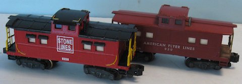
I started, as always, with disassembly. These two cabooses had the body mounted by pins in each corner which must carefully be pried loose and then pulled out with needle nose pliers. The body then almost falls off. Inside, there are a couple of sheets of what was probably white paper at one time, to “diffuse” the light from the single center light bulb. (Actually, the paper looks better from the outside in its aged color than new white paper, so I saved it to use again!)
The window “glass” is thin, clear plastic cards attached to the body, which most also be removed. They are glued onto the body, but age and heat has made the glue less than secure and you can carefully peal the windows off.
The brass end railings/ladders are held by two bent tabs (top and bottom) at each end of the body. Just straighten the tabs and the end parts will pull off.
Other than clean the wheels and electrical pick up tabs, the chassis was set aside to concentrate on the body.
These are fairly plain cars, so you can make a lot of visual impact with a few easy changes. I’ll start with the roof. You might have noticed that there are no roof walk platforms on opposite corners where the brakeman would climb from the ladder to the roof walk itself. I made these out of 1/8” scribed balsa sheet, which is about 1/16” thick with lines scribed 1/8” apart. This is very close to the roof walk plank spacing. I cut the pieces ¼” wide by 5/8” long with the planks,
running the same direction as the roof walk itself. They were then glued into position above the ladder at each end of the car.
I then decided to add roof ribs on the plain roof to give it some texture. These were made out of strips of card stock a little less than 1/8” wide and 13/16” long. They were spaced from each the end of the roof 9/16” apart toward the cupola.
Something I debated, but didn’t do, was lay ¾” wide masking tape on the roof to give the texture of roll roofing.
The last roof top modification was the steel pin stack. This needs a top on it to stop rain from going right down the stack and put out the fire in the conductor’s stove! I used a small piece of brass tubing to create a “T” top for the stack. Small diameter plastic tubing will work too.
On the sides of the car, I made window shades out of 1/8×1/8” strip wood, filed to a triangular cross section and glued above each window. On the cupola, I used a single shade for both side windows. There were no shades for end windows.
Setting these modifications aside, I moved to the stamped end railings/ladder parts. These appeared to be stamped brass, and might have looked really good polished up, but I fought the urge to do that. Unlike very expensive locomotives or flashy passenger cars, cabooses were often rated as barely above freight cars by the railroads. In the era when cabooses were assigned to crews permanently, the men sometimes dressed up “their” cars though.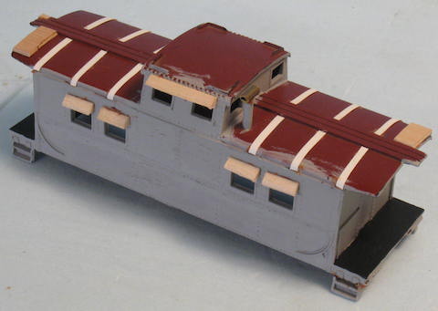
I decided to match the ends to the rest of the car and paint the railings and ladders a more realistic “Safety Yellow.” The brake wheels were left black, and since the curved area of the railing next the brake wheels are actually supposed to be chains, I painted this area black too. This area could be cut out and scale chain placed where it is supposed to be.
The platform and roof tabs on these parts were painted black as well to match my color scheme for the car.
On this one, I decided that my version of a Baltimore and Ohio red car with black roof and platforms would be nice. No, not all of B&O cabooses wore this paint job, but it was very common in the forties and fifties. Handrails on these cabooses were “Safety Yellow” making for a colorful, yet traditional looking “Little Red Caboose.”
The finished paint job was decaled and then given a coat of Testors “Gloss” before re-assembly. The car looks like it is fresh from a shop rebuild (which it is!)
Compared to the original Flyer 930 caboose, the differences are striking!
End – Stumpy Stone
______________________
April 2, 2013
Stumpy’s Station – “The Junkyard” Part One
Way back last Fall, there was brief discussion on the S Trains Yahoo group about making junk cars out of 1/64 scale die cast cars. I gave the subject a brief overview, others added their ideas and experiences, but there is far more to the subject. While admittedly of interest to only a small group of hobbyists in S gauge, it nonetheless is an interesting subject because there are so many other things to be learned on the way to the junkyard.
For instance, before we even get ready to put up the corrugated fence and drag in junkers, there are questions to be answered and a LOT to learn about real cars in order to make the yard as authentic as possible. We’ll start with a very basic question: What year is your layout set in?
When the junkyard scene takes place, you have to have an idea of the era involved. Obviously a junkyard, or the entire layout for that matter, would not have eighties era automobiles in a fifties era scene! We don’t have to be exact here, because setting a time for your railroad can quickly involve the types of buildings you must use and even the billboards will “date” a layout. You wouldn’t have dozens of steel buildings in the early 1900’s or cigarette advertising on a modern day operation!
Nothing sets the era of your railroad better than automobiles, especially in North America! After the end of Model T Ford production, car styling changed every three years, with “facelifts” in between. Therefore your time window could be as narrow as three years! That certainly narrows down “when” your railroad is set in time.
But it need not be quite that precise. Since most “Baby Boomer” modelers like the era when steam was on the way out and diesels were becoming mainstream, let’s say that our sample time frame is the early sixties. This gives you the widest range of railroad equipment to choose from, but also gives you quite a range of automobiles too.
Your streets and roads can have several early sixties cars, and fifties cars in large numbers. Late forties cars will be fewer, and pre-WWII cars will be there, but rare. Anything older than the mid-thirties will be most unusual by then.
However, in a junkyard, there will be some twenties autos, a lot of thirties and forties cars, early fifties cars and maybe a few late fifties cars. Having anything in a small junkyard as modern as three years old was rare then because specialist salvage operators grabbed them.
Cars built in the twenties and thirties will generally be one color, almost always a dark one. Black, Maroon, or dark blue, green, or brown were common. Autos of that era in “two tone” were always the higher end cars, but the combination was usually black or dark color fenders and running boards with lighter body color. The lighter colors were often a medium blue, green, or brown, but sometimes tan, cream, or light green would appear. Sometimes wheels were painted different colors, with red, yellow, and tan being favorites. Vehicles for police and fire departments, or specially painted commercial vehicles would be different of course.
Just before World War Two, some cars started to be painted with the body and fenders a dark color and the tops a lighter color. This style continued into the fifties. But by the mid-fifties, better paint and more color was available and some companies went wild with two and even three tone paint jobs, often in tasteless, even bizarre combinations. Most disgusting of all was a FOUR tone 1958 Nash (Rambler) Ambassador station wagon I saw painted white, yellow, pink, and black from the factory! I certainly hope it was a special order beast! In the early sixties, cooler heads prevailed and paint jobs returned to those designed by Earth people instead of Martians!
Full wheel covers were extremely rare until about 1950 and were uncommon until late in that decade. Most cars had “hub caps” as they had since the twenties to cover the lug bolts that held the wheels on. Some cars from about 1935 onward had “trim rings” which were thin chrome or stainless steel rings around the outer edge of the wheels.
White sidewall tires were limited to high cost cars or as owner purchased replacements until after the war. Those huge “rim to road” white walls were found on late twenties and early thirties Cord, Lincoln, Packard, Cadillac, Auburn, Pierce-Arrow, and Duesenberg cars, but you didn’t find these cars in small junkyards! Otherwise you just didn’t see many white wall tires on older cars in junkyards. If they had them when they were dragged in, and they had any tread left, the yard owner snatched them up right away!
Painted bumpers were standard until the thirties except on high end cars, or by special order. Chrome bumpers on pick up trucks were rare into the late fifties. Even then, they were optional and most pick ups had no rear bumpers unless the owner added one.
End of part 1 – Stumpy Stone
______________________________
May 6, 2013
Stumpy’s Station – “The Junkyard” Part Two
Last time we learned what cars of the twenties through early sixties looked like as manufactured. This time, we’ll step through the gate of a small junkyard typical of the early sixties. Being a “Car Guy” of that era, I was a denizen of the junkyards of the day while looking for parts to restore old cars, build hot rods, or keep Stock Cars running. About ten years ago, I built a small O scale junk yard for a modular club I was in.
Most yards were known as “Mom & Pop” operations. They were far smaller and less business–like than today’s yards! Today’s salvage yard operators will not let you into the yard at all, but you go to a building and ask for parts like a common auto parts store. And you pay a high price for that as well.
Not so in the sixties. In fact if you wanted a part, “Pa” (often in scruffy overalls or blue jeans and dirty t-shirt, would tell you where cars were that had such parts. Sometimes he had a similarly dressed “helper” with fewer functioning brain cells. You carried your own toolbox into the yard and took the parts off yourself! Back at the gate, you’d haggle over a price with “Pa,” and then pay “Ma” at the shack at the gate. Sometimes she would even give you a receipt!
Most yards were surrounded by either a high board or corrugated steel fence with tall weeds growing along it. There was always a gate with a small building of some kind, and not far from it was a garage building, shed, or lean-to, where car stripping was done, bumpers, body parts, and tires stacked, or yard equipment was kept. This structure was generally built like a pole building using the same material as the fence, but sometimes an old barn or other permanent building had been taken over.
Usually, there was a set of cutting torches, a big work bench, and a wall with tools hanging on it. Various jacks and large wood blocks (bits of railroad ties were VERY popular) were nearby to lift and hold up cars.
Junkyard machinery was usually an old farm tractor, a pick up truck at least ten years old, and a “Pole Truck.” The “Pole Truck” (in this era was generally a WWII military surplus “six by”) truck with the bed gone and a tripod of steel pipe welded on. A winch behind the cab supplied a cable that went up over the top of the tripod and ended in a hook. It was a home built “wrecker” to drag and lift cars.
Pavement was virtually non-existent inside the gate. Often, there would be slag or gravel around the gate and building, but otherwise the grounds were just hard packed dirt.
Cars that had been there a long time and were pretty well “picked clean” had tall weeds around them and were generally solid rust in color, their paint long stripped by years exposed to sun, wind, rain, and so on. Often they were missing the hood, which was probably the first thing to go so that the engine could be more easily reached. The interiors were had long rotted away because the windows and doors were open or gone.
More “active” cars would generally be surrounded by trampled, dusty ground. They’d be missing wheels or blocked up with those wheels, concrete blocks, or old railroad ties. The hood would be ajar, up, or gone, as would doors, trunk, and windows. Headlights were prized as were taillight lenses, so the fenders had blank holes where those parts had been.
Cars were usually stripped randomly, depending on what parts were needed. Mechanical parts were the most common thing to go first, but front fenders and hoods would sometimes sell quickly as well because most auto accidents damage the front end. Sometimes the entire “front clip” would be gone; hood, fenders, bumper, and radiator support. The rest of the car would be there, with chassis and engine exposed!
Cars could be found on their sides so that chassis parts, transmissions, gas tanks, rear axles, and so on, could be more easily removed. Once in a while, there might even be one upside down! Cars stacked on top of one another was usually done in bigger yards and those cars had been well stripped before they “went on the pile.”
Glass was also a hot item. Old safety glass would turn milky or bubbles would appear between the layers of the glass as it aged. And, of course in the days before seat belts, victims would strike or go through windshields and other windows even in minor accidents. Good glass was always in demand.
Wandering a junkyard was a great lesson in automotive engineering, history, and how cars crumpled in accidents. It could be a real education while you got parts cheap.
End of part 2 – Stumpy Stone
________________________________
June 3, 2013
Stumpy’s Station – “The Junkyard” Part Three
Okay, let’s makes junkers! Plastic cars are harder to find in 1/64 scale, but are easier to disassemble and mangle. For the most part, we have to use die cast cars. Cheapest are the cars from Big Box stores or Dollar stores, which are often clones of those “Hot Wheels” or other toy cars. I try to avoid mangling the better 1/64 scale cars that are very nice and rather expensive, but occasionally that may be necessary.
The first thing you’ll want to do is play junkyard owner and strip your cars. Die cast cars are usually held together with “rivets” underneath. You can drill these out or grind them off with a Dremel tool. Sometimes you’ll get lucky and the car was assembled with screws! Take the car COMPLETELY apart, and set all the parts aside for later use. If the car has working hood or doors, remove them as well. We’ll be doing most work on the body shell and chassis.
In a real junkyard, you would find FAR more cars that have just died and been towed in, than cars that have been wrecked! We’ll start with the “dead” cars because you’ll do most of the same steps to wrecked cars too.
If the headlights and taillights are cast on, cut them off, leaving holes in the fenders. Remove any cast on bumpers. If you want to depict a car with the “front clip” missing, cut that away carefully, saving everything behind the line of the hood and fenders. If you want a door off, cut it away leaving as much of the body as possible. File all ragged edges.
Remember you want the body shell to LOOK like someone unbolted these parts! The removed parts can be kept for a scrap metal pile. Sometimes you can buy toy cars so cheap that you can buy two the same, cut them apart differently, and have hood, fenders, and doors leaning against the body in the yard. The parts you ruined in cutting them off and the body shell you ruined cutting off the “removed parts” become odd wrecked bits for the scrap metal pile.
Another good trick is to cut doors and hoods off carefully, ruining the shell. Next use layers of aluminum foil bent around the part, trim it, and you have a duplicate foil body part! Handle carefully of course. This foil “body panel” can be bent to depict wreck damage and glued onto a ruined shell, or the panel can be lying nearby. Undamaged body panels could be leaning against the wall of the garage or shed.
Most die cast cars cheap enough to mutilate don’t have an engine, but some do. If you cut away a “front clip” you can use an engine sitting there on the chassis. Just paint the engine black as if coated with oil and grime. Use a piece of paper or clothes dryer sheet painted a dull gray over the top of the engine as if it was a cover to keep rain from going into the motor. Otherwise, there can be a group of engines lined up and similarly protected by a cover beside the garage building or inside but visible to onlookers.
Most of the time you won’t need the interior of the die cast car, and some don’t even have one. Most real junkers might have a dashboard still in them, but seats are generally gone or rotten. You might have a few “later model” cars with the front seat inside just for variety. Interiors were most often a lighter or darker color than the paint job, or were black or gray.
You’ll want to “wreck” some cars too! Most people get out a propane torch and have at it. But it’s very easy to go too far with many of the cheaper die cast toys. Just what kind of crash turns a car into a blob?
To get an idea what cars really look like, start watching TV and taking notes, or better yet, hunt down old crash pictures on the Internet. Most wrecks are frontal impacts with trees, walls, or other vehicles, or roll over accidents. In the old days, Rescue crews didn’t cut roofs off, they pried or cut doors open, so you won’t want any roofless cars in your “old” yard.
Use a small torch carefully to soften the metal just enough to bend the metal with pliers. However, if you don’t want to use or don’t have a torch, “cold bending” is very effective too. The idea here is to work slowly using little force. I have done a bit of bending, then let the car sit for an hour to let the metal somewhat “stabilize,” then bend it a bit more. I repeat until the bend is enough, or the part becomes over stressed and breaks.
Breaking off a part is not the end of the line as you can glue it back on, in the “crash” position, and round the edges with a file and body putty to make it look bent.
More “wrecking” next time!
End of part 3 – Stumpy Stone
_____________________________
June 2, 2013
Stumpy’s Station – ‘The Junkyard” Part Four
Last time we were into wrecking cars, so we’ll “take up where we left off.” Another way to create dents is to use a Dremel with a grinding stone on it. You just grind into the body the make and shape a dent. If you grind through the body, just fill the hole from the back side and sand the outside to shape.
If you want to mash a large panel such as a roof or trunk, sometimes you have to use a hammer. NO! Not a large one! If you want to take your frustrations out on something, don’t do it on the car! In wrecking (or for that matter weathering or scenery) less is more.
Make a wooden block that fits under the car to support the body area and work the area with a small hammer. The block helps support the die cast metal as you stress it. Work slowly and carefully. If you do break the roof, you might save it by gluing it back in place in a damaged position. File rough edges and use putty to smooth it up and round things off to look like bent areas.
Whether the car was wrecked or just “died,” it will be partially stripped in a junkyard. Perhaps the side trim will be gone on one side, but not the other. A door handle may be gone, hood ornaments, wipers, glass, and other small parts might be as well. All cars got disassembled at random as customers took only the parts they needed off them. If you needed the door trim on the right side, why take the one on the left side too? Parts cost money, even at a junkyard.
These parts are almost always part of the body casting and will have to be carefully filed or ground off. You might even go so far as drill or use a toothpick to paint tiny holes where there parts were because that’s what you would see without that part on the body. You can create “rust out” by drilling or filing rough edges around wheel openings and under the doors.
Once you have done all the “surgery” on the body shell and parts, it’s time to start painting. I sand the entire body shell to smooth marks made by hammers, pliers, and grinding, then paint the shell and chassis inside and out with red primer or Tuscan red-brown to give finish some grip and create the illusion of old rust. Do any “parts” except “glass” or tires too.
Different metals “rust” to different shades of color. Cast iron; engine blocks, transmissions, rear ends, are darker than sheet metal; fenders doors, and so on. “Newer” rust is also a lighter color than “old” rust too!
If you are going to install windows or seat and dash board, prepare them now. Missing windows are common, so cut one or more off the plastic “glass” part. Cracked glass is left behind. You can easily scratch “cracks” into the plastic “glass” with a hobby knife. If the car is a wreck, remove or crack the glass toward the point of impact.
If there was one, replace the dashboard and steering wheel already painted similar to the final body color but a different shade. If you want to put the front seat in, paint it the same color as the dash before installing. Don’t bother with the rest of the interior.
You can now reassemble the junk car. Forget rivets and screws to mate body to chassis, use glue or epoxy.
The junker has been sitting in the yard for a long time, so the color paint would be well worn. The older the car, the longer it will have sat deteriorating. Such a car could remain completely rust coated. By the late fifties a thirties car would fit this appearance.
Later cars would show thin paint on the roof hood, trunk, and tops of fenders. Dry brush the selected paint color in these areas and paint normally on the sides and ends of the body. There is no need for gloss paint or an air brush here! The paint of the day dulled quickly if not regularly cared for!
Using a toothpick, you can paint “rust spots” here and there, mostly a few on upper surfaces, more around wheel openings and the bottoms of fenders. Paint silver the chrome on remaining trim parts, hood ornaments, door handles, and bumpers. Side trim was often stainless steel, but other parts were chrome plated steel and would show “rust spots” on them. Remember, less is more in weathering!
You might want to add dust and rain streaks if you’re good at weathering, but only enough to give the SUGGESTION of long exposure.
While you’re at it, modify and weather the junkyard’s vehicles too. They are usually just repaired junk equipment and little thought was given to appearance, just keep them running. They will have dents and rust too, as well as spilled oil and some grime.
In our final installment, we’ll “dress the set!”
End of Part 4 – Stumpy Stone
______________________________
August 2, 2013
Stumpy’s Station – “The Junkyard” Part Five
We have the cars, we have spare parts to place, we know what a small yard was like from the earlier parts of this series, but how do we make our own scene?
First of all, how big an area do you have, or need? The junkyard that I built about ten years ago in O scale for the modular club could have been 8×21,” in other words, almost a whole module except for track area. In that much space, even in O scale, I could have built a sizable yard!
As it was, I chose to do a small yard, just enough to give a flavor of such an operation, not a full scale representation. I used a piece of thin wood veneer as a base and made it 6×12” which allowed a two stall garage, a gate shack, and room for just a few cars.
In S scale you could go a bit smaller. Or of course any size, if you really enjoy this project and have built a dozen or more cars. Perhaps build a large yard with all kinds of salvage besides automobiles, and run a siding into it equipped with a magnetic crane.
A small junkyard could have about six junkers spread around with spaces between a couple of them as if a car or two had been stripped out completely and cut up.
Almost all of the old yards I’ve been in used corrugated metal sheeting for the perimeter fence with wooden posts and stringers. Making the wood part could be done with scale lumber, but being basically cheap, I bought a whole pack of kabob sticks for under two bucks at the grocery store.
Scale corrugated metal panels are available and expensive, but I stumbled onto a “Corrugating Tool” in the Scrap Booking area of a local craft store. Using common card stock (3×5” file cards, also from the craft store) I “rolled” my own corrugated metal fencing. I cut the cardstock to 8 scale feet high and sent it through the tool. This was laid on the work table and the kabob sticks cut to 6 scale foot lengths and glued on as posts. These posts go from the “ground” to a point below the top of the fencing. Other kabob sticks go between these horizontally as stringers. Actually, the stringers are much heavier than they should be in S scale, so perhaps scale lumber would work better for them.
I made enough fence to surround the yard and decided to do my garage the same way. It had no windows or doors, the “front” was open so you could see the structure and vehicle and junk inside.
All timber on the fence and in the building was painted with a dark wood stain I had left over from a furniture project, and then the corrugated sheeting was painted with gray primer. After the primer had dried, I dry brushed rust streaks down it and in some places did a “wash” of rust color over the whole surface. As with all weathering, less is more, it is very easy to overdo! After this weathering, the fence was glued in place and the garage was assembled and placed.
For the gate shack, I used a small shed kit and painted and weathered it well. The gate itself was built similarly to the corrugated fence and glued in the open position.
I spread some light gray ballast at the entrance to the yard, inside and in front of the garage building. The rest of the yard was painted tan to represent dry dirt. Around the fence (on both sides) I dabbed green paint. Once I decided which junk cars would go where, the most stripped ones had green dabbed where they would go, under the “active” cars were left “dirt.”
I next placed the junk cars and glued ground foam weeds in the green areas along the fence and around the older, more stripped cars. Fenders and doors, tires and wheels and bits of painted aluminum foil “sheet metal” bits were then randomly placed to create debris. A stack of tires was put near the garage as was an engine. Placing “clutter” can be an art form.
I did not glue my “Pole Truck” in place so that I could move it from time to time. I made it from a die cast Model AA stake bed truck with the bed cut off and the tripod made of Plastruct plastic “pipe.” This also was “dented” and had lots of rust spots and grime on it.
If you add people, you’ll have to do some painting on available figures, but this will be adding smudges of oil, or dirt. Customers would be common male figures in t-shirt nad blue jeans. You might want to paint bib overalls on a couple of them to represent “Pa” and his helper. “Ma” could be out of sight inside the gate shack, counting money.
For many of you a few junk cars behind a gas station would be enough, while I know of at least one S gauger who turned such a project into a large operation loading scrap onto gondola cars with a crane!
Turning toy cars like “Hot Wheels” into realistic ones, or creating junk cars can be addictive once you get into it, especially if you like cars to begin with. Adding such a “sub-hobby” to trains can be lots of fun!
End of Part 5 – Stumpy Stone
______________________________
September 3, 2012
Stumpy’s Station – “Project Atlantic” Part One
Beginning this month, I’m returning to Kit Bashing old American Flyer locomotives as the subject. I have gotten some requests from those who have read my “Kit Bashing American Flyer Steam Locomotives” guide and still feel hesitant to try it, to do a series that takes the process step by step.
For those of you who have not read the guide, it is available right here on MyFlyerTrains in the photo Albums.
Much of this series will cover ground I’ve already covered in the “guide” but perhaps doing it a step at a time will make the process clearer. I’ll add photos to further remove the “mystery” of doing what collectors might consider a “black art.”
To start the process, you can do as I often do and start looking through junk boxes at train shows or ask to see a hobby shop’s junk boxes. As I have said before, sometimes you’ll be surprised at what you find, and often you can buy the whole box for the same price as one or two items. Keep any usable items you find for a future project you haven’t even considered yet. You only badly need something when you don’t have it!
If you don’t feel comfortable in repairing and rebuilding, then perhaps purchasing a complete and running steamer of less than pristine appearance would be the way to go. In this case, a common Atlantic is the target project locomotive, and these are plentiful and cheap in running condition.
When looking for a usable engine, you’ll want to know what you are looking for. The Atlantic covers virtually the entire production history of American Flyer from the end of World War Two until the demise and purchase by “hated competitor” Lionel in 1966. Therefore it came in many variations, but certain ones are more desirable than others when it comes to Kit Bashing.
I avoid the pre-1952 #300, 302, 302AC, and the early 1952 #300 Atlantics because they have a metal boiler shell. Most of these early Atlantics also do not have smoke and Choo-choo because the reverse unit was commonly in the boiler. Only the 1950 #302AC with the single piece metal shell has these desirable items.
It’s up to you, but I also discount the early engines because of the sheet metal tenders with the link style couplers. Beware that early 1952 production had “tin” tenders, while later ones had plastic tenders, but both had links.
If you like the “extended smokebox” look of the early #300 with the four piece metal shell and extra valve gear, and don’t want to do anything more than paint and decal it, you can get smoke and Choo-choo by swapping a later chassis into the early shell. You might have to drill out the inside of the smoke stack of the metal shell to do this too.
There are many later Atlantics with the plastic boiler and tender shells. I like plastic because it is MUCH easier to cut, drill, sand, and glue than metal. However, some of these plastic boiler shell engines don’t have smoke units or Choo-choo, some don’t even have a headlight!
Of these later ones I avoid the 1953 #301 because it has no smoke unit. The same goes for the rare #299 of 1954. The #307, #308 and 21160 are also without smoke.
The #303, #21100, 21105, and the #21107 were all equipped with headlight, smoke, Choo-choo and knuckle couplers, making them my choice. Note that from the later #21105 of 1958 on, the boiler shell had the whistle and bell molded on, not separate. The #21107 had PikeMaster all plastic trucks and couplers.
Of course the #21160 and #21161 are priced beyond reach and shouldn’t be used as Kit Bashing fodder because of their rarity. The desirable Atlantics for Bashing (#303, 21100, 21105, and even the lowly #21107) are all inexpensive in running condition, with $50. just about the upper limit for our needs. $25. to $40. is a good price for bashing stock. However prices are ever climbing.
People ask why I don’t bash the cheap and common “Casey Jones.” Well, I did two of those, and found them to be poor candidates. The cabs are well out of scale, being more suitable for 027 Lionel. Worse yet is that they are poor runners, a “bargain basement” of cheesy design and construction. The tender is useful for other projects as it is the common “fits all” plastic one. I also have cut up the boiler shells to get the pilot (cow catcher), stack, headlight, and domes to “back date” other projects. When the price of an entire running locomotive and tender in nice shape is less than a good boiler shell for an Atlantic, that should speak volumes!
Okay gang, now you know what to look for, let the hunt begin! Next month we’ll tear your new victim apart and get started!
End of Part 1 – Stumpy Stone
________________________________
October 5, 2012
Stumpy’s Station – “Project Atlantic” Part Two
The first thing to do when you have your project engine is to disassemble the locomotive partially by removing the tender from the engine and taking the shell off the locomotive. If you plan to install a DC can motor while you’re at it, you’ll want to take the tender shell off as well.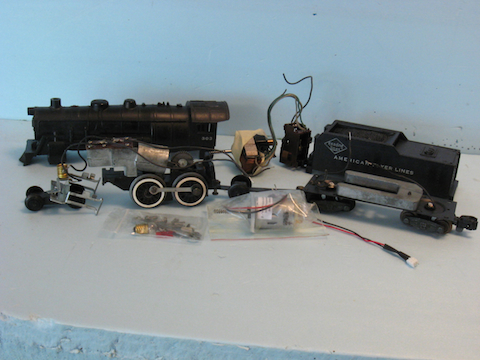
Depending on the condition you purchased your locomotive in, you’ll want to clean and inspect the chassis and all working components. It will not be necessary to take everything apart, in fact unless you have to, a good cleaning of the assembled chassis and mechanism with a used tooth brush is a good way to do the job. Unless the seller has done a good job, you’ll find most of these engines dirty and oily under the shell, often with a nice collection of lint. Most of this crud was attracted by lubricants.
Don’t use soap and water on the chassis and mechanisms. A good spray electrical parts cleaner or WD-40 can helps the toothbrush. Both the pressure from the can and the solvents themselves help get tight spots clean and will dry/evaporate cleaner with no residue. If you’re working with junk box parts that are rusted, PB Blaster or any good penetrating oil will work, but they leave oily residue that must be removed.
Flip the locomotive chassis over and do the bottom too! Take the gear cover off and look at the mess in the gearbox! Usually years of old grease and oil have hardened into a nearly solid mass that is no longer doing any lubricating, but IS attracting dirty and small metal particles. If you find steel wool “hairs’ this could spell real trouble for motor, gears, Choo-choo unit, and even create hard to find short circuits.
Clean the gearbox out (a very small screwdriver is useful) and use electrical parts cleaner and a small cloth to get as much of the inside of the area clean as possible.
Inspect the engine and tender chassis’ closely after cleaning. While the actual Kit Bashing is mainly “cosmetic,” you want the finished product to run as good as it looks don’t you? Any repairs should be done now.
You should also re-lube the gearbox with a good lubricant. A Teflon “grease” is my favorite because it will last a long time and doesn’t attract crud as easily as the all petroleum products. Just a heavy smear on the axle gear is enough. Don’t use grease anywhere else. You can also use oil
if done from above where the worm gear of the motor touches the axle gear. Again, Teflon oil is available and worthwhile.
Lube the gear and lever for the Choo-choo unit with oil, but DO NOT lubricate the unit’s piston and cylinder unless it is dry and binds, and if you do, put oil on your finger or a Q-Tip and spread it around thinly. Oil the axles, side rods and such to complete the lubrication.
If the plastic boiler and tender shells are dirty, another used toothbrush and plain old soap and water are the way to go. Dirty parts are a mess to work with, and paint won’t adhere to oil or dirt.
If you’re installing a DC can motor, remove the old motor field and armature from the chassis. You will have to cut or de-solder the wires to the smoke unit and headlight. The brushes will spring out if you can’t hold the armature inside the field, so work over a tray or pan to catch flying parts! You will find tiny washers where the motor shaft goes into the chassis. Save these to put back in with the can motor. Remove the reverse unit in the tender as well. I just leave the motor and unit wired together, even if there is a plug board between.
Installing the can motor is straightforward and simple. Put the tiny washers on the shaft and slide the worm gear shaft in slowly while allowing the axle gear to turn and mesh. Use the screws that come with the replacement motor, but do not over tighten them. Some engines like at least one just a tad free for best gear mesh until the gears are broken in. To complete installation, solder the smoke and headlight wires and positive and negative wires for the tender to the lugs on motor. Use a very flexible wire for the motor to tender connection.
If you’re going to run straight DC power all you have to do is solder wires from each tender truck to each wire coming from the motor. If using an electronic reverse unit to run AC track power, follow the instructions for that unit carefully. I like to put a miniature connector between engine and tender for ease of uncoupling for later service or repair.
Okay, the engine is clean and in top condition running wise. Now the real butchery can begin!
End of Part 2 – Stumpy Stone
_______________________________
November 7, 2012
Stumpy’s Station – “Project Atlantic” Part Three
The changes being made are for demonstration purposes. You may want to leave the loco as it is in some cases or come up with other modifications. You’ll notice that in the photos, sometimes the areas being worked on will be painted primer gray while other times the work area will be black. This is only done to make the work stand out for the photographs.
Using “primer” paint is an old auto body working technique to highlight any very small dents, sanding scratches, or other imperfections. You sand and primer, sand and primer, spotting bad spots and filling scars until the surface is up to standard. Gray primer works best for most model projects. During cleaning the shell, I removed the bell, whistle, and headlight lens. They are all just a “press fit” into the shell with no glue having been used. Light prying with a small screwdriver will usually pop them out. The headlight lens is most stubborn, and the best way to remove it is to put a small screwdriver or dowel inside the cab and push it out from behind. Sometimes it will need the help of a small hammer to knock the screwdriver or dowel ahead to push out the lens.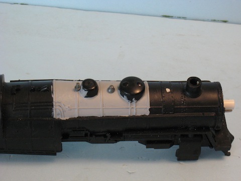
The bell was originally located between the stack and front dome on the boiler top. But I’m going to move it to a spot between the domes. The bell can be moved simply by drilling a 1/8” hole in the top of the boiler between the domes. If you stop the drill before full penetration through the shell, a press fit will be enough to hold it in position. You’ll want to file off the “ring” around where the bell was, fill the hole with putty, and sand it smooth. At this point however, we’ll not install the bell because these small parts will go on after final color is applied.
The whistle was originally mounted above the firebox area of the boiler shell, and on the original Atlantic is just fine. But most engines had the whistle straight up and near or on the steam dome, and that’s where it’s going. I drilled a 1/16” hole (some whistles have a 1/16” mounting pin and some have the 1/8” pin, so check which you have first) right behind the dome between the dome itself and the boiler band behind it. Cut and file off the original whistle mount on the boiler. For now, don’t install the whistle either.
Now, the first big cutting begins by moving the headlight from the top front of the boiler (smokebox) to the center. Using a hobby saw or Dremel tool with a “cut off wheel,” CAREFULLY remove the old headlight. Do as little damage as possible to surrounding bolt heads, smokebox door lugs, or classification lamps. Smooth the area with sandpaper, but work carefully as you’ll be repairing any damage you do.
Fill the empty hole with a piece of plastic rod, dowel, or putty it closed and sand smooth. To represent the bolts around the boiler front and damage to the smokebox door lugs, I use drops of white glue from a toothpick. It may take some practice to get these just right, but it works well. A couple of coats of primer seals these to the boiler.
Next, drill a 1/16” hole directly in the center of the boiler front where the new headlight will go. This is a “pilot hole” to make sure you’re located right, you next drill a 3/16” hole in the same spot. You’ll need a piece of plastic or metal tubing at the hobby shop or online that fits the original headlight lens. This will be 3/16” ID (inside diameter).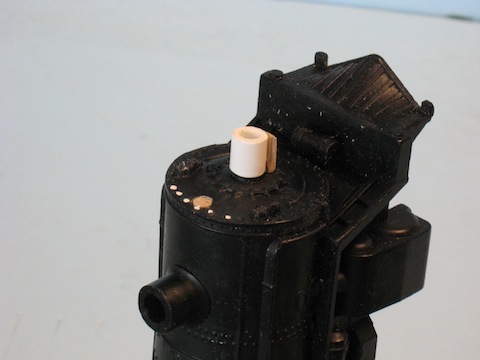
Depending on what you use, you will sometimes have to file the inside of the tubing and the hole in the boiler front a bit, or fill it a little to get the right fit.
In a pinch, I have used plastic drink straws split and wrapped in layers around the lens stem and it works amazingly well! A friend used to make headlights in HO scale out of black electrical tape wrapped around plastic rod to make headlights!
Use a small piece of plastic or strip wood stock to make a headlight bracket to go under the headlight itself. Glue the bracket to the bottom of the headlight and when that dries, the whole assembly to the front of the boiler shell over the hole. You want a nice tight fit to the boiler front. I find typical home improvement store adhesives which “glue anything to anything” fine in most cases.
If you were able to use the tubing method, leave the lens out for now. If you used the wrap method, use masking tape to cover the lens so you won’t get paint on it.
Okay, you’ve changed the profile of the locomotive somewhat, but there is more to come!
End of Part 3 – Stumpy Stone
_______________________________
December 1, 2012
Stumpy’s Station – “Project Atlantic” Part Four
Often times when I’m waiting for paint or glue to dry, I move on to another project, many times the tender of the locomotive that I’m working on.
The post-“tin tender” Atlantics were followed by the common plastic Gilbert tender. These appear to all be the same, but they are not.
The drawbars used to attach tender to loco were different lengths, and those tenders behind the “Casey Jones” engines did not have the trailing truck. Even the trailing truck set up on the drawbar changed from the three digit engines and the five digit engines. Later tenders of this type featured a shell attached by a tab at one end and screws at the other instead of a screw in each corner. These were mostly PikeMaster era tenders.
I have even run across some tenders where the rear of coal pile humps slightly above the fuel bunker sides, while on others, the coal is even with the sides. Some tenders have holes for the marker lights at the rear of the tender deck, while on others, these holes were molded flat.
The tender is often overlooked by Kit Bashers, but can help give a different appearance to the loco-tender combination. I often swap tenders form loco to loco during a project, using the K-5 or Hudson cast tenders behind Atlantics or Pacifics.
One of the easiest changes you can make is to “convert” your coal tender to oil. You start with a piece of plastic or balsa sheet 2” wide by 2 5/8” long which covers the fuel bunker top. If you have one of the tenders with the higher hump in the coal, file it down until level with the tender sides.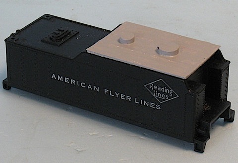
To make a oil fill cap, you can cut a ¼” thick or about that piece of ½” diameter dowel or plastic rod or tubing. You next cut a similar thickness piece of ¼” diameter stock to represent the vent cap. Sand these smooth and set them aside for the moment.
This next step isn’t really necessary, but I think it adds to the appearance of the “oil tank” and will show you a trick long used by scratch builders.
You’ll need a piece of thin card stock, 2” by 2 5/8.” Thin card stock is really just a plain old 3×5” “file card.” They’re cheap and I bought a pack of these some years ago and they lasted for over ten years of modeling projects!
Another investment in you box of hobby tools is to buy a Ponce wheel. You
can get them from Micro-Mark or any craft or sewing store. They are used to mark sewing projects, but we’ll use them to press “rivets” into the card!
On the cardstock, draw lines 1/16” along each edge of the card stock. Then draw two lines, each 5/8” from the sides running the long length of the card. These are you guide lines to press the rivets with the Ponce wheel.
Place the Ponce wheel’s roller on a line and then roll slowly along the line, staying as straight as possible. It doesn’t take a lot of pressure, but you must exert some. You might wish to practice on the remains of the file card which you cut the part for the tender from to get the “feel” first.
By rolling the wheel along, you will find neat rows of equally spaced “bumps” on the other side of the card stock which look very much like S scale rivets!
The next step is to glue this rivet sheet to the top of the tank top sheet you cut at the beginning. When dry, smooth the edges, removing any overhang of card over the base.
Now let’s install the oil filler and vent caps. As far as I can find, there was no uniform arrangement for these, but the best look is to place the larger fill cap between the center and “front” of the oil tank, and the vent aft of the center of the tank along a centerline of the long length of the tank top.
I cut two small strips of cardstock for “hinges” for the fill cap. To show the “bolt heads” I press these with a ball point pen in the same way we used the Ponce wheel. The pen makes a larger “head” impression. These are then glued to the cap and tank top.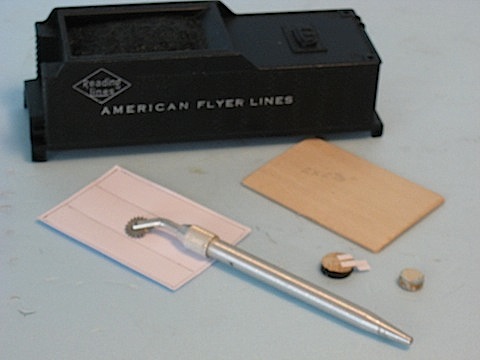
You can glue this permanently to the top of the coal bunker, or do as I do and use Walther’s “GOO” or a silicone adhesive, which will allow you to remove it later if you want to.
Most oil tanks were painted black to match the locomotive and make spills less obvious. However, I have seen photos of engines where they were painted some lighter color like gray. If you chose a lighter color, this would allow you to paint black “spills” on the tank top to show usage.
Of course, with a Wooten firebox, you’d certainly not be burning oil! So you may want to skip the oil tank idea and add more scale coal to the coal pile.
End of Part 4 – Stumpy Stone
______________________________
January 15, 2013
Stumpy’s Station – “Project Atlantic” Part Five
On this project, I wanted to update this engine from the “Turn of the Century” look of the inside bearing trailing truck to the later outside bearing trailing truck. This will require two things; a five digit Pacific two wheel trailing truck and a new drawbar.
In this case, I didn’t have a late Pacific truck in my parts boxes, so I ordered one from LBR Enterprises (www.lbrenterprisesllc.com). It is part number R23 a “2 wheel trailing truck A+P” (Atlantic and Pacific) and is a nicely done repro part.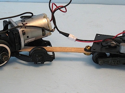
However, the drawbar was something else. There are two ways of coming up with a usable drawbar.
Usually you can use the original drawbar by cutting the rivet that holds the original trailing truck wheels and axle to it. The later trailing truck fits there and pretty much covers the now empty “upside down U” in the drawbar. However, just are all plastic tenders are not the same, neither are all drawbars.
Make your own drawbar of either metal or wood. Use the original drawbar for the length and screw hole placement dimensions.
Since I like to work with wood because it’s easier, I chose to do what has worked for me before and used a Craft Stick, a.k.a. Popcicle Stick. Amazingly, these work fine, although not as durable as metal. A metal drawbar is done by just duplicating the original without the “U” area for the original truck. So, I’ll go into a bit of explanation of the wood trailing truck construction should you wish to try that.
If you do break a wood one, they can be glued right back together until replacement can be accomplished. How do I know this? At the first Spring S Spree where I displayed a layout, my first semi-streamlined Pacific derailed and dove 400 scale feet to the floor! There was damage to the plastic running board skirt, the streamlined pilot, and the drawbar broke in two. I glued the drawbar back together with Elmer’s white glue and ran the damaged loco the next day! The re-glued drawbar was still on the locomotive when I sold it two summers ago. There are some tricks to working with Craft Sticks. First of all, drill any holes and do any filing on them working to the center of the stick lengthwise. After the holes are ready, use a Dremel with cut off wheel to
cut the extra length from the ends.
The reason for this is the way the sticks are made. They have a tendency to split if you drill too close to the ends and cut the sticks with a hobby saw.
For the Atlantic drawbar, you’ll need to drill two holes 3 3/8” apart for the drawbar screws. The locomotive screw requires a 1/8” hole. I used a bolt and nut for the tender end. Make sure the bolt and screw can move freely in their holes, then cut the excess length of the drawbar off.
Of course, to use the replacement drawbar, you’ll have the cut off the rivet that holds the original drawbar to the tender and replace it with a bolt and nut. Test fit the new drawbar to the loco and tender and then paint it black.
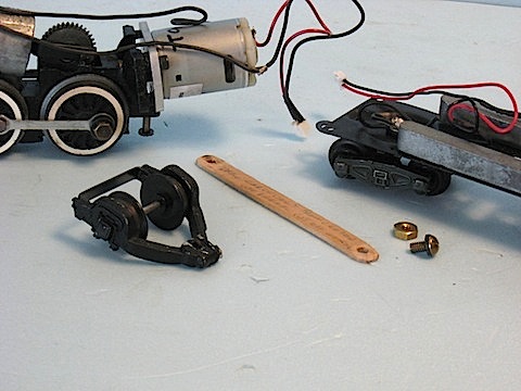
The screw on the engine end of the drawbar is long enough to hold both the new drawbar and the trailing truck. Using the Craft Stick drawbar, you may have to file away some of the thickness of the trailing truck around the screw hole to allow for free and up and down movement. I had a problem with only one such change of drawbar and trailing truck with this long screw backing out from the vibration of running. I solved it by putting a glob of paint on the threads of the screw then running it through the drawbar and truck and into the engine. After allowing this to set for a few hours, the screw never came loose again. Unlike some thread locking products, this screw will come back out with light twisting of a screwdriver if need be.
I placed the drawbar on top of the tongue of the tender truck, used a very short bolt and nut on the tender end, and did the paint glob thread locking trick on it just to be sure. You need tighten only to the point that the drawbar can just swing freely. You can now put chassis and tender together for some test running without the engine or tender shells, if you wish to.
Normally, we’d be ready to start the painting and lettering of the Project Atlantic. However, there is one more modification I want to tell you about that takes us into the realm of major custom building.
For this, you’ll need a junk plastic 280 series Pacific shell. The screw posts inside can be totally destroyed, but you want one that looks decent on the outside. Next month we’ll remove the wide Wooten firebox from the Atlantic and graft on the standard firebox and cab of the Pacific! Warm up your Dremel and buy a package of good epoxy if you want to try this!
End of Part 5 – Stumpy Stone
_______________________________
Feb 4, 2013
Stumpy’s Station – “Project Atlantic” Part Six
And now we do some serious work that many of you may wish to pass up. In this installment, we will go beyond the point of no return on this project by sectioning two old shells into one! This modification is time consuming and requires you to work slowly and carefully.
We’re going to change the project locomotive by removing the wide “Wooten” firebox and the cab and replace it with the firebox and cab of a junk plastic 280 series Pacific shell. The mounting points for the Atlantic shell are not going to be touched, eliminating a complicated procedure, and the portions cut off both shells will be the same length. The key is finding a junk Pacific shell with the firebox and cab area intact. Usually this will be one with the mounting posts broken and unrepairable, which are not needed for this project anyway!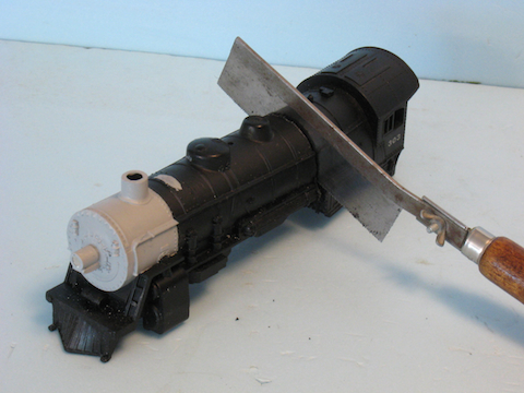
We will cut the Atlantic’s shell right at the front of the wide firebox, which is a bit behind the rear mounting points. To make sure you cut as straight as possible, measure back from the boiler front because the firebox front is not exactly vertical. You want to cut at the bottom of the front of the firebox, which actually is slightly forward of the rest of the front of this firebox and not “straight up.”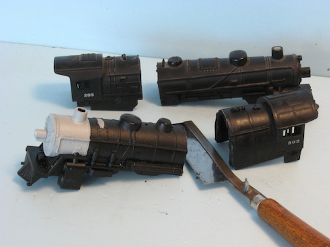
Measure the removed firebox and cab section and cut the Pacific shell firebox and cab the same length. Once the two are removed, match the front of the Atlantic boiler shell to the rear of the Pacific boiler shell. You’ll find that the Pacific boiler is a bit wider toward the bottom than the Atlantic boiler, and that the various pipes and lines molded on the boilers will not line up.
I filed and fitted the two shell sections as closely together as possible, and then turned my attention to removing the running boards and other detail cast onto the firebox area of the Pacific shell. I left the details on top of the firebox and the steps on the side intact, but removed the rest. It is much easier to do this removal now than when the two sections are
glued together. Do not use putty or primer paint on the mating surfaces because you’ll need them “clean” to glue together.
You’ll find yourself doing a LOT of very careful cutting, filing, and sanding these details off and smoothing the scratches and damage made in the
removal. It will not be perfect. Because the lower part of the boiler is wider than the Atlantic boiler, you’ll want to file some angle into this area
to help it mate closer in width. However, there will be some bulge at this point which cannot be avoidable. All this takes the most time of all the things you’ll do on this part of the project and I used a LOT of primer paint and sandpaper on this step. I never did get it “show car” nice.
Once the Pacific shell section is ready, it’s time to glue the two shells together. In this case I used J B Weld, an epoxy with a slow setting time for maximum strength. Faster epoxies are available, but generally the strength of the slower ones is better, and the slower setting time allows you to make adjustments before the glue sets. I used the J B Weld with the 15 to 24 hour curing time and allowed a full 24 hours.
To start with, I prepared the work table with several layers of old newspaper to catch any dripping epoxy. Next, I blocked the Atlantic shell into position, making sure the blocking was not too near the area to be epoxied. Then used masking tape to tape the top of the boilers together, allowing the Pacific portion to be swung away for gluing.
Then I applied the epoxy to the Pacific section and swung the part into position, making sure that I aligned the top of the boiler and got the sides as close as possible to square, using the tape to hold the Pacific portion in position. I slipped some blocking into place where the epoxy wouldn’t get to it and left the work table and project until the next evening.
J B Weld is sandable, filable, drillable, and so on, so anything that might get stuck by accident can be cut or filed away. This is also good if some epoxy squeezes out of the joint to where you could see it on the completed model. Cut, file, and sand this. The inside doesn’t have to look as good, just clear the chassis and motor when you attach the shell to the chassis.
To fill the gap where the two sections go together, use model putty and do the sanding, primer painting, sanding, painting cycle until the joint is invisible. The gray primer will show up any imperfections.
If you do choose to make this radical, tough, and time consuming modification, it will be well worth all the worry and effort when people notice your “one of a kind Atlantic” for the first time!
End of Part 6 – Stumpy Stone
______________________________
August 3, 2012
Stumpy’s Station – Back To Bashing!
If all goes according to plan, next month we return to Kit Bashing old Flyer steam engines. This time I’ll take you through the process step by step, with photos, of modifications to a cheap and plentiful Atlantic.
First we’ll discuss which ones are preferable for Kit Bashing, move to clean up and inspection of the chassis of the locomotive and tender, installation of a DC can motor, and then we take a Dremel tool the shell itself and make changes small and large.
You might ask why I’ll start with selecting a suitable engine and why you’d want to disassemble the engine. Well, not all Flyer Atlantics were created equal! There were dozens of variations over the twenty year production of these locomotives, and some are just poorly suited for Bashing. Of course, this long production history is what makes the Atlantic so plentiful and inexpensive, a perfect combination for a first Kit Bash.
While some of you have done Flyer repairs before and may be comfortable buying from junk boxes, for others this may be their first time inside the locomotive. The better “deal” you get price-wise, the more likely you’ll have some unseen trouble inside. Since there is little point of doing a lot of cosmetic work and then discovering the locomotive has mechanical or electrical problems that don’t allow it to run well, I advise finding and fixing running problems first.
Most times even better vendors at train shows won’t have cleaned up the inside of a lowly Atlantic. All that dirty and hardened crud can effect the operation of the engine. But you can’t just dump the engine and tender in the dishwasher and expect it to work out! (Although while I worked at the hobby shop a woman who wanted to sell us her husband’s old trains did just that! With disastrous results!)
There are right ways and wrong ways to clean certain components and things to look out for which could cause problems down the track. Reassembly and lubrication is also going to be covered.
While basic painting and decaling would normally be the easiest thing to do, and where most of you would start with your first simple changes to the appearance of old American Flyer steam locomotives, we’ll wrap up the series with that! Why? Because most of the changes we’re make will require cutting, drilling, putty, filing, and sanding, so there’s no point painting and decaling before finishing all the “body work.”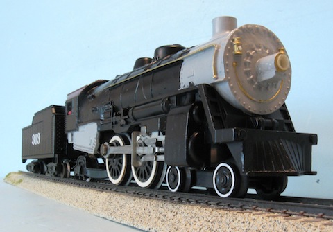
We’re going to make a few easy changes, such as moving the bell and whistle to different locations. Do some middle level changes such as moving the headlight from the top of the boiler front to the center. And I plan to make a drastic change to the wide Wooten firebox.
Now, a word about installing a DC can motor; I come mostly from the “model” side of trains. One of the major differences between “toy” and “model” trains is that “toy” trains run on Alternating Current, while “model” trains run on Direct Current. With AC power, you are required to carry an on board reversing unit to change the locomotive’s direction. With old American Flyer, this item can be problematic, often sticking, and impairment prone to dirt and rust.
With DC can motor power, no such device is needed. By throwing a switch on the power pack, the locomotive changes direction with out going through a “forward-neutral-back” cycle. The advantages are; ease of operation, less electrical drain through the reverse unit, and no problematic reverse unit to tinker with. Besides, the old motors are tired, draw more current, and run hotter than the modern can motors.
To provide DC track power you can buy a large DC power pack such as those used for G scale trains, or you can add a rectifier and direction switch between your AC transformer and the track to create DC track power.
The modern DC packs are expensive, but put everything in one convenient package that gives much finer control than any transformer. The combination of old AC transformer, rectifier, and electrical switch is much cheaper, but requires you to fashion a box for the rectifier and switch, and start-stop speed control is not as good.
I’ve included some tips about the DC can motor installation simply to give you that option to consider. After all, when you Kit Bash, there’s no going back to original anyway.
And so, that’s what is coming up here at STUMPY’S STATION as we move into Fall. I hope you will add this series to the information you already have by reading my “Kit Bashing American Flyer Steam Locomotives” guide available here on MyFlyerTrains. Enjoy!
Stumpy Stone
___________________________
July 6, 2012
Stumpy’s Station – The Perfect Layout?
One of the “Holy Grails” of model railroading is to find the perfect track plan and build the perfect layout. I have chased this dream for years in N, HO, S, O, and G scales, including the narrow gauges for most. I have built about 35 layouts for myself and for/with friends, indoors and outdoors, and I have even built small ones for sale at the local hobby shop.
Of these 35, a large number were never finished! I’m sure that a number of you have been through the same thing. Yes, I’ve heard the same story that you have that “a good layout is never done,” but that’s not what I mean.
I’ve spent hours looking at magazines and track planning books. When computers came along, I tried track planning software. I’ve drawn layouts on paper and even tried to lay them out with sectional track on a blank sheet of plywood. I’ve made most of the mistakes one can make, and on the next layout, I find there are more to make!
I have built fairly basic ovals, point to point switching layouts, two levels with grades, small layouts, and large layouts. I have gone to many home layouts to see what others had done, or were doing, and found them with the same problems that I faced.
I have come to the conclusion that there is no such thing as the “Perfect Layout!” And as proof, let me tell you about some things I have learned NOT to do in planning and building a layout.
The first thing the typical model train guy is faced with is that “I don’t have enough space to build a nice layout.” We’ve all been there, the thinking that “if we just had a little more” (or a LOT more) we’d be fine. I’m sorry to burst your bubble, but size isn’t the problem.
I have built garden railways that took up a good sized portion of back yards and there is NEVER enough space! I helped a friend lay out and build a massive garden railway which took up an entire LARGE back and side yard. Had his wife not stopped him, the entire home would have been completely surrounded by track!
I spent about a year helping another guy build his HO “basement filling empire” and all we got done was all the bench work and most of the track down before the project began to slow down. After running trains on the finished trackage, we discovered a number of flaws in the plan and eventually the progress ground to a halt.
Worse yet, Chuck had started with a branchline logging and mining theme for the layout, but had changed interests during construction to heavy mainline operations! The winding single track layout was unsuitable for this of course.
I have visited a few home layouts that were literally a “Monster in the Basement” because the semi finished but operating layout took so much time to maintain that there was no time left to finish or run it!
And so, the number one lesson is that the huge layout is NOT the “Perfect Layout!” Too expensive to build in time and money, too much maintenance, and because of this it becomes an object of dread to work on rather than a fun hobby, it never gets done.
At the other extreme is the Micro Layout. These are very small but highly detailed little railroads, which are cheap and quick to build, and require little time to maintain. If you get tired of one layout theme or track plan, you build another Micro Layout to a different theme!
But they’re not the “Perfect Layout” either! Because of the small size, track curvature is very tight and you have to use small locos and cars. Sorry, no modern Husky Stacks, or even large steam locos and long passenger cars here.
The closest thing I’ve seen to “perfect” was an old buddy’s HO Home Modular Layout. It started with four corner modules with fairly generic scenery in 1991, and then expanded for years with straight modules. As his interests changed, new modules were built to that interest. He would even rearrange all the modules from time to time to change the way the layout operated.
When he tired of a certain module, he’d swap it out for a new one. The entire layout grew and shrunk as he changed modules and overall shape from square, to rectangle, and back again. Not long before he died in 2006, he was “rediscovering” a few of the older modules and swapping them back into the layout!
So is there really a “Perfect Layout?” Heck no! And there never will be! But there’s always the dream.
Stumpy Stone
_________________________
July 5, 2012
Stumpy’s Station – “Questions”
I’m going to do something a little different this month. Over the years, people have e-mailed me to ask many questions. Here is a random sample of some of them:
Many folks new to American Flyer trains have often asked why did Flyer put those “Wide White Wall” wheel rims on their steam locomotive drivers? The reference is often to the large area of white rubber on automobile tires of the same era known by that nickname. In the case of Gilbert, it was to insulate the metal wheels from electrical conductivity. However, “Wide White Walls” are actually very prototypical, if overblown by Gilbert! The real steam railroads did exactly the same thing, but for other reasons. Replacing the drivers on a steam loco is a major operation, so early on, the manufacturers began mounting “tires” on them. The drive wheels themselves would not be subject to wear if these “tires” were between them and the rail. These rings of metal could be removed and replaced rather than removing and replacing the drive wheels. At first attempts were made to mount these driver tires with bolt or rivets, which soon became unsatisfactory. The solution to this problem was to heat the tire, causing it to expand slightly. Then mount it while hot to the driver itself. The tire cooled and “shrunk” onto the wheel, needing no other form of fastener. In some cases, lead and trailing truck wheels were also fitted with tires, and a few wheel manufacturers offered “tired” rims on rolling stock wheels.
One of the problems with driver tires was failure from wear or damage, particularly dangerous at high speed! Broken off pieces of the tire could be thrown many yards, destroying anything which they encountered, including engine crewmen! A broken driver tire could also lead to a derailment, as these tires were also the flanged part of the driver. Well-worn tires could detach from the wheel at speed as well, and only a few engineers got their trains stopped safely when this happened. Regular inspection was vital, and to help spot flaws and cracks, the driver tires were often painted white, light gray, or silver so that these problems could be more easily spotted. In the days of highly decorated locomotives, all the wheel rims on the engine and tender would be painted, a trend which ended when locomotive fleets got too big to keep up such decoration and became all black. However, many Class One passenger locomotives and some short lines with a small locomotive fleet painted all the wheel rims right up to the end of steam. Even large fleets painted driver tires for years after the rest of the engine was black.
Why was a Fireman needed on a diesel locomotive?
The Fireman was a key crewmember on steam of course. He stoked the boiler or operated the automatic stoker to fire the boiler, kept and eye on boiler pressure, cleaned flues with blasts of sand on oil fired engines, watered and fueled the engine at stops, and did light maintenance and repair. When diesels came along, things changed, but the Fireman did more than just ride! Many people forget that the early diesel locomotives were frail and cantankerous machines. Most railroads, which would even try a diesel in the early years, saw them as barely useful for switching in rail yards where they were near repair facilities. They were much less powerful than steam locos and far less reliable. The first “road” diesels were tried on new streamlined passenger trains in the mid thirties. Even pulling lightweight trains like the Burlington Zephyr and the Union Pacific M-10,000 were the peak of internal combustion on the rails at the time. Steam handled most “serious” passenger trains and all freight. Both the locomotive manufacturers and the railroads were sure that diesels “would never replace steam for heavy freight trains.”
But the diesels got better, with more railroads trying them for limited passenger train use. They still broke down fairly often and lacked the horsepower of steam, and the first Firemen on diesels had to be re-trained to handle different equipment. In a way, they were like the “Riding Mechanic” of the early days of automobile racing. They watched the gauges, watched the track, and did repairs. The Electro-Motive “FT” demonstrator set of four diesel units made the final diesel breakthrough by hauling freight. This “building block” approach to adding horsepower and reliability was long proven on electric railways, and confronted steam seriously for the first time in its strongest use. The rest is history. But even then, the Fireman had much to do. For instance, the shutters and fans for cooling were manually operated on some “First Generation” diesels. The Fireman watched the engine temperature gauges and opened and closed the shutters or turned fans on and off as needed! Instead of boiler pressure, he had to keep an eye on oil pressure. He handled the on board steam heater for the passenger cars which were still steam heated. He had to do running repairs and dozens of other chores, just as he had on steam locos. It would be the sixties before a Fireman was no longer required.
What’s the real story of Casey Jones?
Over 100 years after the famous wreck on the Illinois Central, it is hard to separate fact from legend. However, we can say for certain that John Luther “Casey” Jones was running too fast on that fateful night, trying to “make up time” lost previously on the run of passenger train Number One. Too fast to stop when he was confronted by the track ahead blocked by two freight trains and lost his life trying to stop. He “died at the throttle” saving the people on the train, and the legend was started as the tale was told around engine houses far and wide. In truth, such wrecks were not at all unusual, and most of the time the engine crew died. Train speeds were going up faster than safety equipment and signaling could keep up. Knuckle couplers and air brakes were only then “new fangled” equipment and not yet used on all railroads. Casey came to the Illinois Central known as a competent engineer and a “fast runner.” These were the racecar drivers or jet pilots of their day, handling the largest, most powerful, and fastest machines on the planet. Some were good, some were lucky, some were just maniacs when it came to “fast running.” Casey appears to have fit both of the first two descriptions. He graduated quickly from freight to passenger operations and gained a reputation for getting more out of a locomotive than others could. John Luther Jones was well liked by fellow employees and management and went on to be active in the Union and Lodge. By all accounts, he was a kind and friendly man, but willing to take a stand if he felt strongly about something. No question an outstanding individual. We must also understand there was a double standard in railroad operation of the day. “Speeding” was strictly forbidden by company rules. However, if you got away with it and kept a train on schedule, you were a hero with management. If you messed up and got killed wrecking their train, you were a worthless scoundrel and all blame was heaped upon you. Even today, this happens with truck and bus drivers and airline pilots. Need to deflect blame for an accident? Call it “Pilot Error!” Casey was both good at his job and lucky in his death. He got the train slowed before impact so that no one was killed in the wreck but himself. Therefore, he attained legend status instead of being written off as a no good. Considering the romantic times, he was indeed a hero!
Stumpy Stone
__________________________________
May 13, 2012
Stumpy’s Station – “Operation”
Having been around for a long time, and coming from the “scale” side of the hobby, one of the things I became familiar with was “operation.” This is a “scale model railroad” term for switching cars and delivering products to different points on the layout. Once you tire of trains going around and around, this is the next step up the ladder. Many model railroaders even create “waybills” so there is actual paperwork to tell you what is in a car and where it is to be delivered.
Now if you load and unload with operating accessories, this is really not a problem, open cars are part of the fun. But if you’re not into accessories, open cars can be a bit unrealistic going around and around the layout with the same load. This is a problem faced in N, HO, and narrow gauge “model” railroading.
Probably the easiest solution is to use trains of closed cars where you can’t see if they are full or empty. You can see if a hopper car is loaded or unloaded, but you can’t see if a boxcar is loaded or unloaded. Or a refrigerator car, a covered hopper, a tank car, or even a cattle car in some cases.
Here’s an example; Let’s say you have a very basic layout. It’s just an oval with a siding on the front straight and another on the back straight. You want to “operate” freight between these two sidings, but you are using no accessories, just buildings. You can use a couple of boxcars on each siding. On one side of the layout is a factory, and on the other a warehouse.
You imagine that the boxcars leave the factory “loaded,” make a few laps to rack up some “distance” and then are set out at the warehouse to be “unloaded.” You also pick up the cars that were at the warehouse, which were “unloaded” and take them to the factory to be “loaded.” Because you can’t see into the boxcars, there’s no tip off when they’re loaded or empty.
You could do something similar with reefers, perhaps loading at a small brewery and unloading at a beer distributor.
Or you could use tank cars loading at an oil storage “tank farm,” and being delivered to a gas station for unloading. Again, you can’t tell if the cars are full or empty.
You can even use different types of cars. Suppose you have covered hoppers loading grain at a grain elevator for delivery to a bakery, and boxcars at the bakery to take the baked goods away.
To make this even more believable, you could add a third siding as an “Interchange Track.” This is a siding with perhaps a small office only, where
two railroads interchange cars from railroad to railroad. The “other railroad” could be at the other end of the siding and “off layout.”
Still another easy spot to load and unload different types of cars is the “Team Track.” Any type of car can be placed here for loading or unloading into trucks for movement to a business not serviced by the railroad. The name “Team Track” goes back to the days when teams of horses pulled freight wagons to trackside to pick up goods.
This does not mean that you can’t run trains of all types of cars. You just switch the closed cars to the various sidings and their “industries.” The cars you’re not switching are “running through to another destination.”
If you ARE using operating accessories, you can use them too, putting cars into trains to have logs loaded and dumped at the sawmill, or coal loaded and dumped at a fuel dealer. The sawmill might need boxcars to take milled lumber away and that fuel dealer might also take delivery of tank cars too.
Of course, passenger trains are treated the same way as closed freight cars, all you need are two stations for the “local” or “commuter” train to stop at. And, if you can come up with two operating stations, you actually CAN load and unload passengers.
It’s all up to your imagination! And don’t be ashamed to “pretend” this loading and unloading is going on, “model” railroaders have played this game for decades!
While the example I gave of the small oval layout is basic, you can quickly see how you can make much more of these ideas with a bigger layout, perhaps switching many cars to many sidings for loading and unloading. By using Team Tracks and Interchange Tracks, you can get even more variety in your “operations.”
If you have a layout with an engine terminal, you might even have space for a “work train” to do track maintenance. Every once in a while, this train will have to run around the layout, perhaps even stop at sidings or block the mainline for emergency repairs for a time. Maintaining the right of way is yet another part of “operations.”
Perhaps another time I’ll get into making your own waybills and dispatching plans to add to the realism of running your railroad.
…Stumpy Stone
_________________________________
April 6, 2012
Stumpy’s Station – “Compressibility”
A lot of us in S gauge have space problems. Oh yes, there are many basement or attic filling empires, and spare rooms allow for good size layouts as well. But not everyone has the space to go beyond 4×8’ basic layouts.
No matter how much space a model railroader in any scale has, it never seems to be enough! After seeing large layouts in the magazines for so many years, we have been “taught” that “bigger is better.” That unless you can run three or four trains at a time, have plenty of structures and scenery, your railroad is “second rate.”
To get all those “requirements” onto a small layout, you really have to jam things in, and pretty soon, it looks like a spaghetti bowl of track in a junkyard. That may be quite well for someone who just runs toy trains, but if you have even the slightest knowledge of real railroads, this won’t do. If you have an artistic eye, it looks bad too.
I hear folks saying; “But there’s no other way!”
You’re wrong! There are alternatives to either a gigantic, maintenance devouring layout, or a tight knot of track and buildings. But it will require an adjustment of attitude and some “thinking outside the box.” You also have to decide just what you want your layout to look like.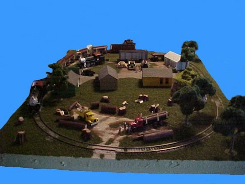
Planning is the MOST important factor for a successful railroad.
Do you like to run trains? Do you want to switch cars and service industries? Are buildings or scenery more important to you? Think about this, because as soon as you lay down the track, you’re stuck with that design.
Even on large layouts, there is such a thing as “selective compression” in order to fit things where they need to be. “Selective compression” or “compressibility” is the art of making something smaller than it really should be. For instance, some scale modelers try to model an entire “division” of their favorite prototype railroad on their layout. But even in N gauge, to really accomplish this could take a basement as big as a basketball court! Therefore, they choose what to model and what to leave out.
Now, let’s take that many steps forward. For instance a 4×8’ layout. Make a list of everything you want to have on your layout. Then measure how much space each will require, including where the track will go. The space each accessory or structure takes up is called its “footprint.” If a station’s base measures 4”” by 7”, that is it’s footprint.
I think the space requirements will be a real eye opener for many! But it is not a disqualifying offense! Go back to the list and start deciding what are your “must haves” from all the things you would like to have. Measure the footprints and track plan again. Rearrange the track or buildings and try again.
Yeah, I thought so! Now cut your actual “needs” from those “must haves.” At some point you will find out what is realistic for your available space. This is often very depressing. Go away for a day to “cool off” and then return to your planning.
You can draw designs on paper for years, but when it comes down to actual building and laying track, the reality sets in with a vengeance! But now that you know just what will fit, you can work out a way to do it, and do it well.
Yes, I know that most of you think that you can’t really make a nice layout in 4×8 feet, but my first S gauge display layout was just 34” by 54” and depicted a logging area and a small town! It was a single track line with one siding and used 15” radius curves. It always drew a crowd at shows because of the well thought out selection and placement of structures vehicles, people and scenery.
The biggest S display layout I’ve built so far is only 4×8 feet! And I have gone even smaller in On30 by building Micro Layouts for display. Micros are the ultimate in “selective compression” and there is a yearly competition for building an operating layout in a large pizza box! If you want to see what can REALLY be done in small spaces, go to Carl Arendt’s Micro Layouts website at www.carendt.us
You probably will never build anything as small as a Micro Layout, but you CAN get some great ideas for use in S gauge! Even if you do have a whole basement to fill, there are things to learn. And if you have a smaller space don’t despair, you CAN build a nice layout.
While we’d all like to have all the space we need to build our dream layout, there are real advantages to building small; It’s easier, faster, cheaper, and requires less maintenance after completion! Plus, if you get tired of your layout, you can dismantle it and build another one with minimal loss!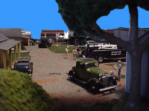
The photos were both taken of the same layout to point out that small spaces can be interesting. This was my second S display layout and was only 36×49 inches with 15” radius curves.
…Stumpy Stone
_____________________________
May 9, 2012
STUMPY’S STATION – “The Illusionists”
Probably the best known of these was Harry Houdini, who was a Magician, Illusionist, and Escape Artist. Aside from his stage career, he also was an author, early movie actor, and debunker of fake spirit mediums. There is also evidence that he worked with Scotland Yard and the budding British MI-6 spy organization on his European tours.
Few in the world of magic today can boast such accomplishments. But outside of the realm of magic and the world of spying, there is another and much, much larger group of illusionists: Model Railroaders.
You’re surprised? Don’t be! Isn’t that what we are doing once “playing with trains” extends beyond watching a toy train run in circle around Christmas? When we advance into the area of creating a train layout, we are creating our own little world. From exact scale modelers recreating a true to life section of a real railroad, to folks who put together a miniature world of their own, we are creating an ILLUSION of the real world!
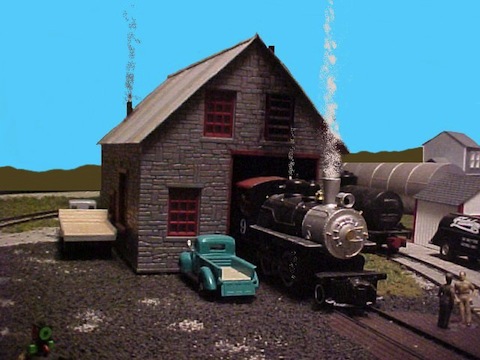
Even the most rabid “rivet counter” must use imagination to believe that those little models are to some extent “real.” It is, after all, just an illusion.
I used to try to build very accurate models, even placing in a couple of train show model contests. But after years of trying to do that in HO, I slowly “burned out” on it. By the time I tried G scale Garden Railroading, I decided that I was not having fun. My modeling was as stressful as the job I was working. After two stress related heart attacks in 1997, both at work, I decided that I’d had enough!
I realized slowly that no matter how hard anyone tries, they cannot recreate the real world! It was all a fake, a sham of reality, an illusion. And then it hit me; It’s like making a movie! Movies are perhaps the ultimate illusion of reality! Many of the buildings are just false fronts, scenery was on a “set,” spectacular action just “special effects.”
From that moment on, I looked at model trains in a completely different way. But it was not until I got into On30 for a second time in 1998 that I found a way to really exercise the “movie set” concept of model railroading. It came about by discovering “Micro Layouts” and Carl Arendt’s Micro Layout website (carendt.us). Here was a REALLY small world of train layouts that were measured in inches instead of feet! People working on them had mastered the concept of creating illusions of a world bigger than it was. I was hooked!
When I returned to S gauge for the third time in my hobby life in 2000, there was no question that I would be a “Hi-Rail” practitioner! Where else could you find the operational reliability of big wheel flanges and couplers, and yet strive to find the realism of “scale” railroading?
I quickly developed my “Hi-Rail Philosophy” that pretty much was to produce the movie set illusion of a scene or layout without worrying about building all the details! As a former “scale” guy and having a library of books and videos of steam era railroading and narrow gauge, I knew what these things were supposed to be like. So “faking it” would be fairly simple.
I have built and dismantled or sold three S Hi-rail display layouts since 2000. These have been to several train shows and every S Spree since 2005. They are illusions, looking “movie set realistic.” And there is no reason that anyone else can’t do something similar on their own layout.
Step back and take a look at what creates the illusion of reality. You’ll quickly discover than many details can’t even be perceived from more than a few inches away, that building interiors are virtually invisible, that under body details on rolling stock can only be seen if you have a spectacular train wreck!
The point is that you need not get bogged down with the details unless that is your specialty! Few people seeing your railroad won’t notice them unless you point them out anyway. But they will be impressed by a nice looking layout with unique items on it. Every loco, every car, every structure creates the special illusion that is yours!
WE’RE ALL ILLUSIONISTS! We’re creating a world that WE imagine, WE build or kit bash, that WE control. This isn’t “rocket science,” this is common sense and having fun with your hobby!
This is escaping the real world for a time, learning new skills, the satisfaction of accomplishment, creating something no one else has because it cannot be purchased at a store or on the Internet!
You and I are “The Illusionists” of S gauge! Welcome to what is, so far, a somewhat exclusive club.
…Stumpy Stone
_____________________________
January 1. 2012
Stumpy’s Station – Build Your Own Models by Terry “Stumpy” Stone
Well folks, if all goes according to plan, this will become a regular feature here at MyFlyerTrains.org, thanks to Chuck Harrington’s kind invitation. And since this is the first one, let me give you an idea of what you’ll be finding here in the future.
It seems that I have found a nitch in the S gauge world by being a champion of all that collectors and rivet counter despise, Kit Bashing and model building using basic materials. I suspect there are one or more “Stumpy Voodoo Dolls” out there, because it seems that every time I write something even the tiniest bit controversial, I get these shooting pains in my rear parts!
I’m not sure why this is, I have built just about all my kit bashes out of junk box finds, and have never condoned butchering rare items. I also don’t think much of people which get hold of complete locomotives and strip them down for parts to sell like some low rent Flyer “chop shop”.
Ouch! There’s that pain again! A new group doesn’t like me. 🙂
I also get some nasty e-mails from rivet counters for not adhering to exact scale fidelity or prototype. Well guys, after years of being a “scale” modeler, I have tired of the hassle and am looking for the fun! And, after all, that’s why I’m in a hobby!
As we progress through these “essays,” there will be some history, stories, humor, and a lot of encouragement to strike out on your own and do something which satisfies YOU! It’s YOUR railroad, your miniature world, do it your way!
We’ll be talking about Kit Bashing. Sometimes that means spending time hunting down locos, cars, parts, and usable materials just like those guys in “American Pickers,” that’s fine! There is the “thrill of the chase,” and the “triumph of the find.” Not only have I done this with model building, but during my years racing Stock Cars and building Hot Rods. Wandering through the old “Mom and Pop” junkyards in search of car parts was part of my hobby world. The goodies are where you find them!
In S gauge, I usually cruise around a train show, checking the tables in my first lap, and then checking UNDER the tables on the second. Often what is on the tables can be an indicator of what might be under them. Many times the seller will give you terrific bargain for the stuff underneath, sometimes you can get a whole box for what you expect to pay for a single item!
Here’s a tip; TAKE THE WHOLE BOX IF THE DEAL IS RIGHT! You get the item you want, a box to carry it in, and a bunch of other stuff you just might need down the road for another project! You just never know when that Hudson tender shell or those Plasticville windows might come in handy.
What do you do when you decide you have too much? Last year I had built up seven large boxes of parts and pieces. That was more than enough to store. So I went through them all, set aside one or two of anything usable, and came up with three boxes to sell. I priced the stuff cheap and ran a “Thinning the Herd Sale.”
This also works for locomotives, rolling stock, and structures too. I have been in every scale from Z up to “ride on” size (7 ½” gauge) and you just can’t keep everything when you change scales. So I “blew it out” in a similar sale at a train show.
The guys at the hobby shop I used to work at always asked why I sold things so cheap? Well, it was simple; I needed money for the new scale, had no place or reason to keep the old stuff, and I didn’t want to spend the rest of my life trying to get top price. Better to get a little than waste a lot time and money carrying the stuff around to train shows for years. After all, I’m not in a hobby to make money, someone else is welcome to that stress.
I’m also asked why I use common materials and build things rather than just buy kits or ready to run items? Well, you must remember I was started on this trail back when there weren’t many R-T-R items. I also had a father who was a professional model builder for a time, and I learned from him. Money was also tight, so we made things out of common stuff.
Dad was a master at this, even when working for the company. He used those round Quaker Oats cereal boxes as oil storage tanks, sandpaper to make shingles or rolled roofing for buildings, dowels from the lumber yard for dock pilings, air tanks, and logs, lots of 3×5” file cards, and probably a ton of balsa wood over the years.
The possibilities are endless. But today we have it much easier with wood pre-cut to dimensionally correct sizes, excellent plastic structural shapes, and all sorts of detail parts! You can build from scratch today more easily than you could build many kits years ago!
So along with the other stuff, there will be a lot of articles here about building things. Some of you may recall the series I did for S Gaugian a couple of years ago on layout building. Well, I might even do some articles about that here as well!
With the economy as it is, you can save yourself a lot of money by learning to use your imagination and your hands, instead of your wallet! And, you’ll have the personal satisfaction of building it yourself! I’ll be explaining how to do that and how even someone with no experience can build models! You CAN do it! Don’t be afraid, I’ll help!
See you next time.
…Stumpy
_________________________